Apparatus and method for monitoring a spatial area, in particular for safeguarding a hazardous area of an automatically operated installation

a technology for automatically operating installations and apparatus, which is applied in the field of apparatus and methods for monitoring spatial areas, can solve the problems of not being suitable for safeguarding automatically operating installations, affecting the safety of automatic operation, and complex installation of light barriers, etc., and achieves the effect of increasing failsafety and little complexity

Active Publication Date: 2008-11-06
PILZ (COMPANY)
View PDF11 Cites 91 Cited by
  • Summary
  • Abstract
  • Description
  • Claims
  • Application Information

AI Technical Summary

Benefits of technology

[0013]Against this background, it is an object of the present invention to provide a low-cost apparatus and a method for monitoring a spatial area and in particular for safeguarding a hazardous area of an automatically operated installation. It is another object to provide such an apparatus and method with an increased fail-safety and little complexity, when propagation time measurements are used for determining distances.

Problems solved by technology

For example, the installation of light barriers is rather complex since the transmitters and receivers, which are at a distance from one another, must be exactly aligned.
However, safeguarding is still achieved by a largely predefined and fixed “fence”, i.e. a dynamic boundary around the hazardous area is possible only to a very limited extent.
This apparatus and method, however, do not seem suitable for safeguarding automatically operating installations since the determination of the distance values may be subject to errors which cannot be detected.
Methods for three-dimensional scene analysis, unfortunately, require a high computational effort, making a real-time implementation difficult and expensive.
Because, however, the propagation times of the light wave are extremely short, these methods have the disadvantage that the stability of the signal processing and propagation times in the associated electronic circuits is subject to very stringent requirements, and changes in the electrical propagation times, such as changes resulting from temperature influences and aging, must be taken into account by continuous calibration.
In other words, all propagation time measurements are subject to ambiguities which endanger reliable distance determination.
When the light is reflected from such a retro-reflector to the image recording unit, this can easily lead to the installation being shut down even though the situation is not dangerous.
On the other hand, in the worst case, this can even lead to a necessary shut down not being carried out, or not being carried out in good time.

Method used


Image

  • Apparatus and method for monitoring a spatial area, in particular for safeguarding a hazardous area of an automatically operated installation
  • Apparatus and method for monitoring a spatial area, in particular for safeguarding a hazardous area of an automatically operated installation
  • Apparatus and method for monitoring a spatial area, in particular for safeguarding a hazardous area of an automatically operated installation

Examples


Embodiment Construction

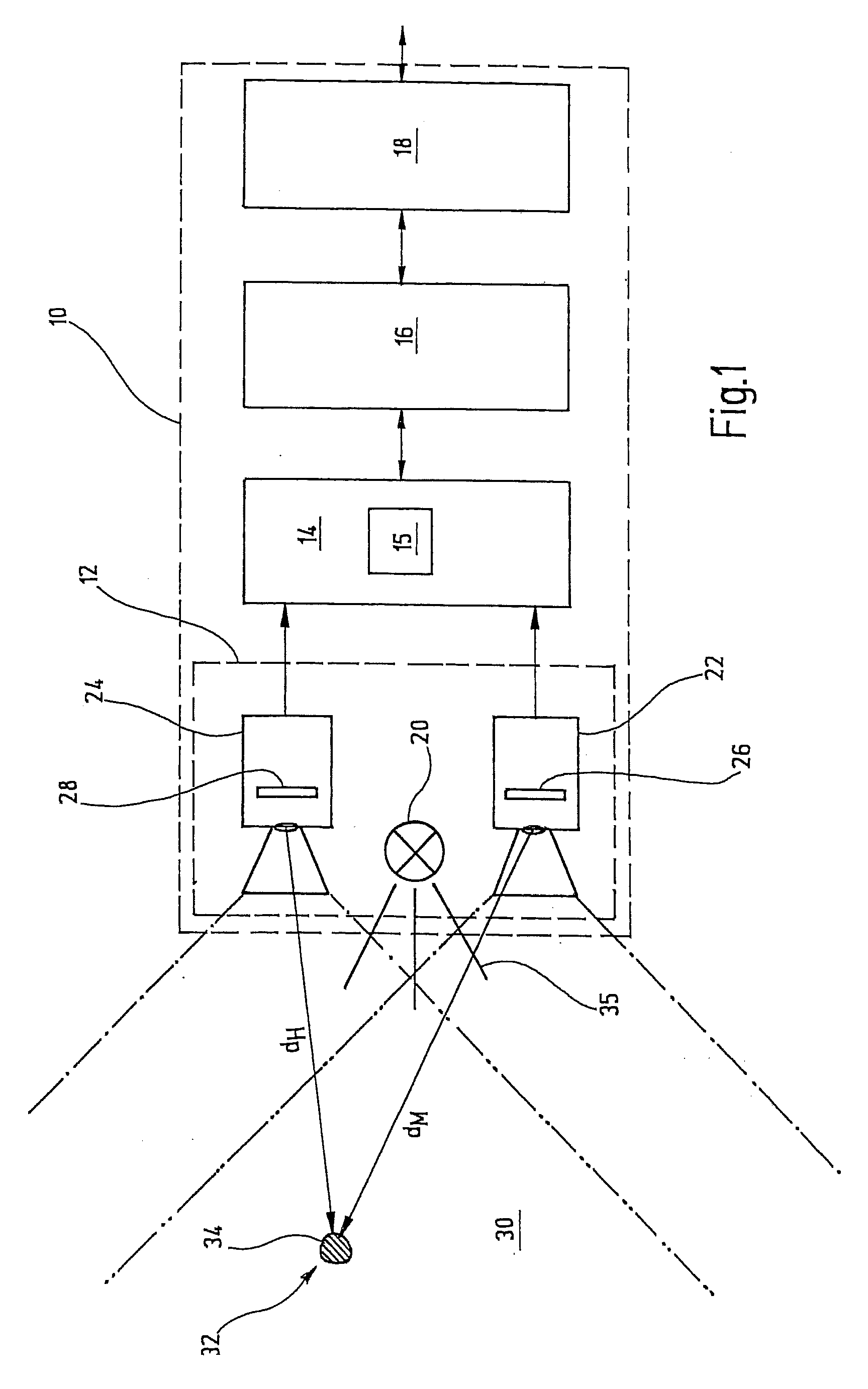
[0041]In FIG. 1, an exemplary embodiment of an apparatus according to the invention is designated in its entirety by reference number 10.

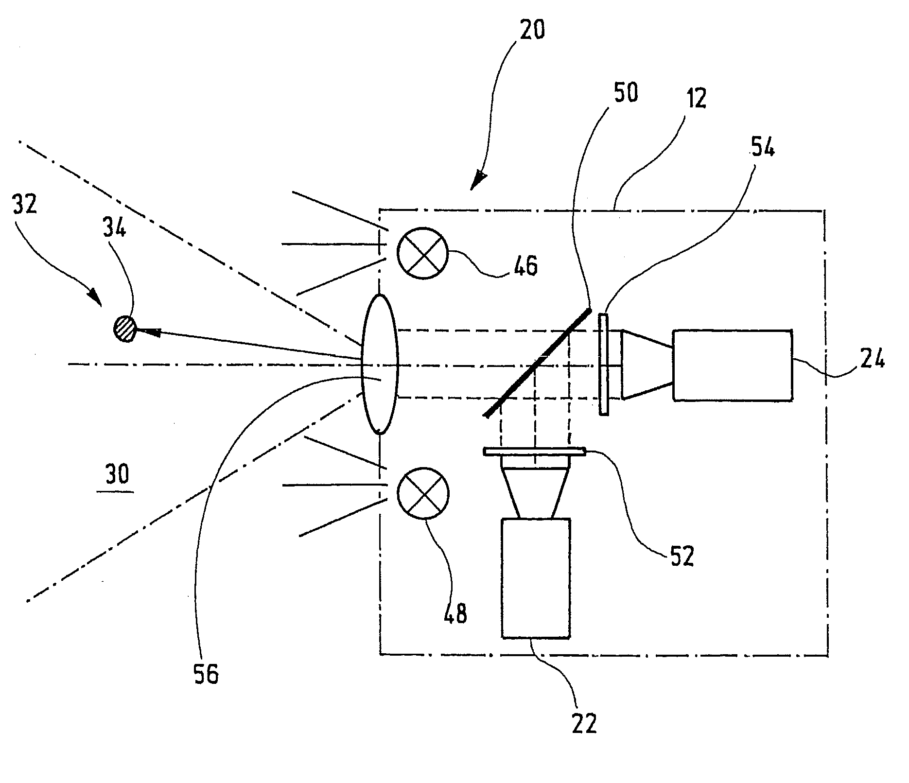
[0042]The apparatus 10 comprises a sensor part 12, an evaluation unit 14 including a test device 15, a control unit 16, and a connecting unit 18. The sensor part 12 has an illumination device 20, a first camera 22 and a second camera 24. The first camera 22 comprises a first image sensor 26, and the second camera 24 comprises a second image sensor 28, with each image sensor 26, 28 having a plurality of pixels arranged like a matrix with respect to one another. In addition, each camera has imaging optics, which define an optical coverage range. The two coverage ranges of the first and second camera 22, 24 are illustrated by dashed-dotted lines, with a common coverage range 30 resulting from the overlap of the individual coverage ranges of the two cameras being symbolically represented by a dashed-double-dotted line. An object 32 is located within th...


PUM


Abstract

An apparatus for monitoring a spatial area, in particular for safeguarding a hazardous area of an automatically operated installation, comprises an illumination device which at least temporarily emits light signals into the spatial area. A first image recording unit records a first image of the spatial area. The first image recording unit comprises an image sensor having a plurality of pixels. An evaluation unit determines a distance value for at least one spatial area point, which is located in the spatial area and is imaged on at least one pixel, by means of a propagation type measurement. The propagation type measurement suffers from a limited unambiguity range. Therefore, a test device is designed to check the distance value by means of a reference distance value determined from a second image of said spatial area.

Description

CROSSREFERENCES TO RELATED APPLICATIONS[0001]This application is a continuation of international patent application PCT / EP2006 / 010886, filed on Nov. 14, 2006 designating the U.S., which international patent application has been published in German language as WO 2007 / 054359 and claims priority from German patent application DE 10 2005 056 265.5, filed on Nov. 14, 2005. The entire contents of these priority applications are incorporated herein by reference.BACKGROUND OF THE INVENTION[0002]The present invention relates to an apparatus and a method for monitoring a spatial area on the basis of images of the spatial area. More particularly, the invention relates to an apparatus and a method for safeguarding a hazardous area of an automatically operated installation using cameras for recording images of the area.[0003]Beside mechanical barriers, light barriers and light grids have long been known and are often used for safeguarding a hazardous area of an automatically operated installati...

Claims


Application Information

Patent Timeline
Patent Type & Authority Applications(United States)
IPC IPC(8): G06K9/00G01S17/87G01S17/89
CPCF16P3/14G01C11/06G01S7/497G01S17/08F16P3/142G01S17/89G01V8/20G01S7/4808G01S17/87
Inventor FUCHS, OLIVERWENDLER, MARTINDOETTLING, DIETMAR
Owner PILZ (COMPANY)
Why Eureka
Try Eureka