
Hardened Connector System Including A Translator

Active Publication Date: 2008-11-06
FURAKAWA ELECTRIC NORTH AMERICA INC
View PDF4 Cites 61 Cited by
  • Summary
  • Abstract
  • Description
  • Claims
  • Application Information

AI Technical Summary

Benefits of technology

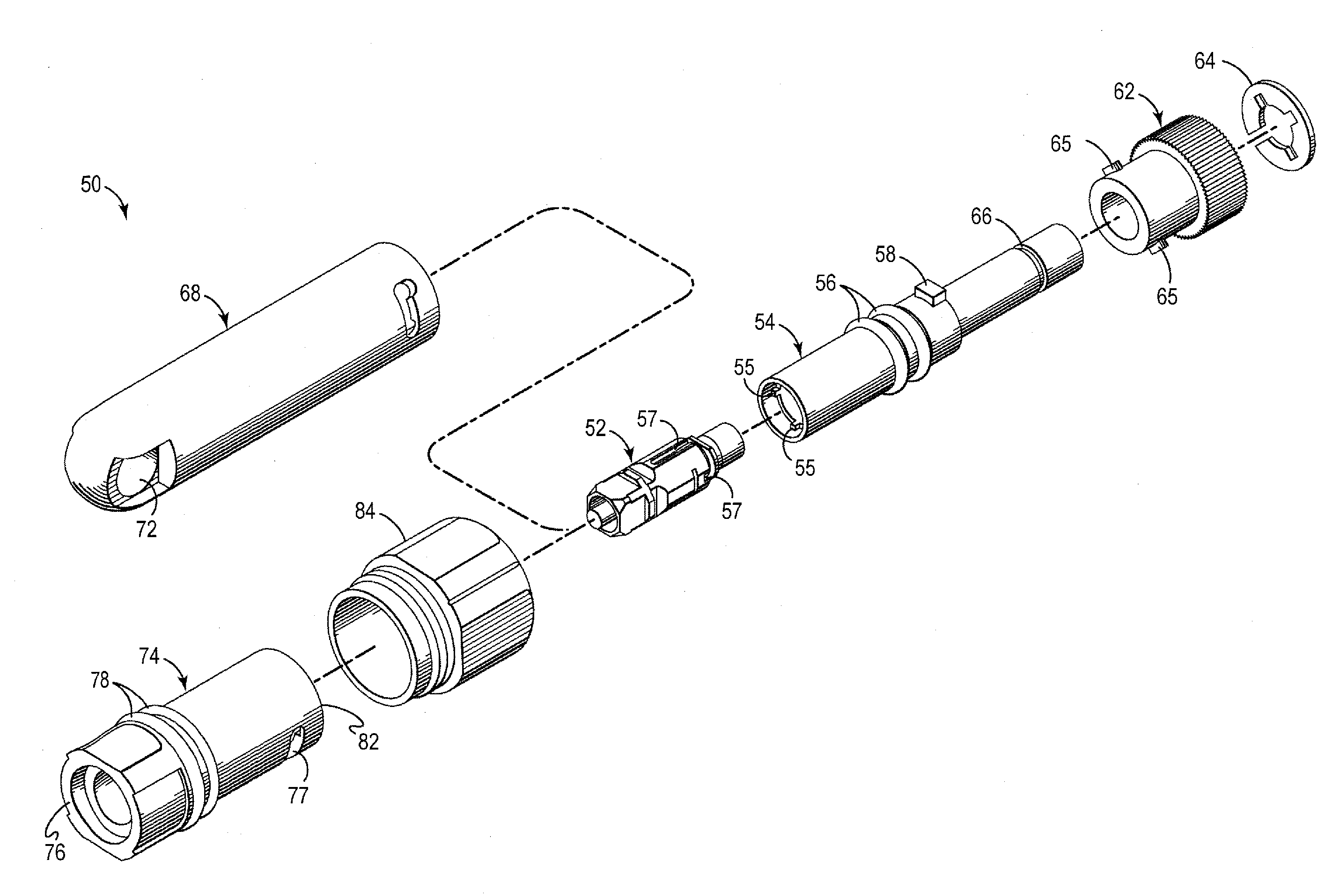
[0010]The invention is embodied in a hardened connector system. The hardened connector system includes a connector plug for terminating an optical fiber, a plug housing for coupling to the optical fiber cable and the connector plug, and a translator for coupling the plug housing and the connector plug to an optical fiber connector adapter. The translator, which has a first end for coupling to the plug housing and a second end for coupling to a jack receptacle portion of the optical fiber connector adapter, couples the plug housing to the optical fiber connector adapter in a way that operably positions the connector plug within the optical fiber connector adapter. Also, the translator is configured in a way that allows the connector, e.g., the connector plug housing and connector plug, to be decoupled from the connector adapter without damaging the connector adapter, e.g., when the connector system is subjected to relatively excessive cable loads. Also, the dimensions and configuration of the plug housing allow it to be pulled through conventional conduit, including a 900 bend in 0.75 inch Schedule 40 conduit.

Problems solved by technology

Also, such connectors typically have a threaded coupling nut, which takes a relatively long time to screw into place compared to other alternatives, such as a push-pull configuration.
Also, when such connectors are subjected to relatively excessive cable loads, e.g., due to ice build up on aerial cables, the connectors sometimes can separate from their corresponding adapters in a manner that permanently damages the adapters, thus requiring the entire adapter to be replaced.

Method used


Image

  • Hardened Connector System Including A Translator
  • Hardened Connector System Including A Translator
  • Hardened Connector System Including A Translator

Examples


Embodiment Construction

[0016]In the following description like reference numerals indicate like components to enhance the understanding of the invention through the description of the drawings. Also, although specific features, configurations and arrangements are discussed hereinbelow, it should be understood that such is done for illustrative purposes only. A person skilled in the relevant art will recognize that other steps, configurations and arrangements are useful without departing from the spirit and scope of the invention.

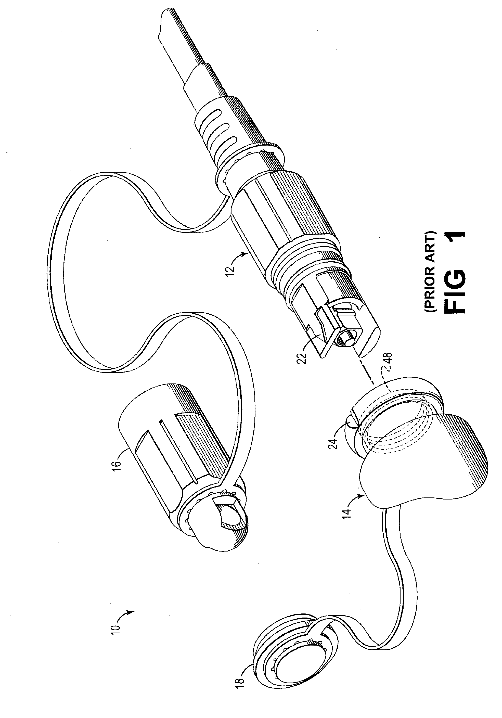
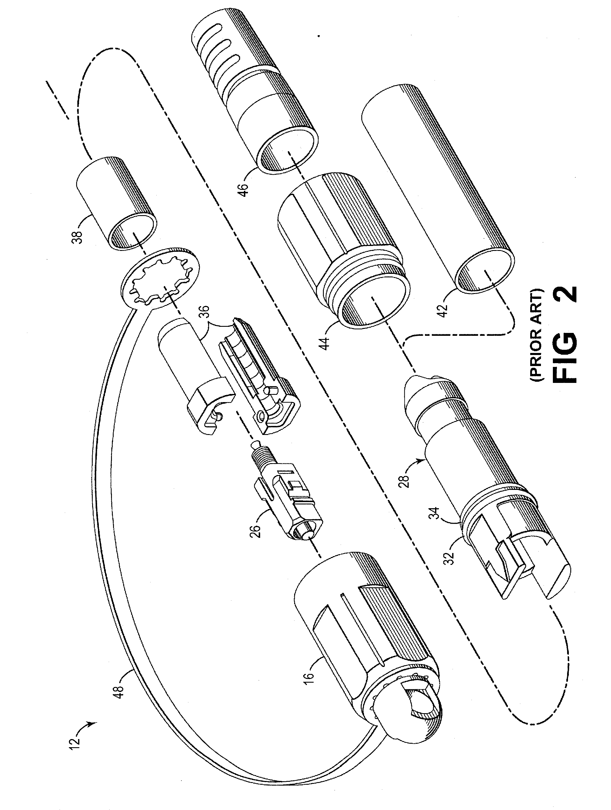
[0017]Referring now to FIG. 1, shown is a simplified, perspective view of a conventional hardened optical connector system 10, in which a first optical fiber connector or connector plug 12 is to be interconnected to a second optical fiber connector or other appropriate optical component (not shown) via an adapter (not shown). The adapter, which typically is pre-installed in a fiber terminal in many hardened connector system arrangements, typically is formed by a jack receptacle 14...


PUM


Abstract

Embodiments of the invention include a hardened connector system. The connector system includes a connector plug for terminating an optical fiber, a plug housing for coupling to the optical fiber cable and the connector plug, and a translator for coupling the plug housing and the connector plug to an optical fiber connector adapter. The translator, which couples the plug housing to a jack receptacle portion of the connector adapter is configured to allow the connector to be decoupled from the connector adapter without damaging the connector adapter, e.g., when the connector system is subjected to relatively excessive cable loads. Also, the dimensions and configuration of the plug housing allow it to be pulled through conventional conduit, including a 90′-bent, 0.75 inch Schedule 40 conduit.

Description

CROSS-REFERENCE TO RELATED APPLICATION[0001]This application claims priority to the filing date of a U.S. provisional patent application having Ser. No. 60 / 927,409, entitled “HARDENED CONNECTOR FOR OUTSIDE PLANT APPLICATIONS”, filed on May 3, 2007, which is incorporated herein by reference in its entirety.BACKGROUND OF THE INVENTION[0002]1. Field of Invention[0003]The invention relates to connectors, such as connectors for use with optical fibers. More particularly, the invention relates to hardened connector systems, such as connectors used in outside plant applications.[0004]2. Description of Related Art[0005]Network providers and customers often need factory terminated, environmentally-sealed, hardened connectors and adapters for use in drop-cable deployments in optical access networks. Also, network providers and customers often desire products that significantly reduce terminal and drop cable installation times and total deployment cost. The connectors and adapters that are use...

Claims


Application Information

Patent Timeline
IPC IPC(8): G02B6/00
CPCG02B6/3816G02B6/3849G02B6/3891G02B6/4465G02B6/545
Inventor BRADLEY, KELVIN B.SIEREVELD, JOHN L.WHITE, WILLARD C.
Owner FURAKAWA ELECTRIC NORTH AMERICA INC
Learn More