Eureka AIR delivers breakthrough ideas for toughest innovation challenges, trusted by R&D personnel around the world.

Dynamically configurable interleaver scheme using at least one dynamically changeable interleaving parameter

Inactive Publication Date: 2008-11-06
REMEC BROADBAND WIRELESS NETWORKS LLC
View PDF26 Cites 12 Cited by
  • Summary
  • Abstract
  • Description
  • Claims
  • Application Information

AI Technical Summary

Benefits of technology

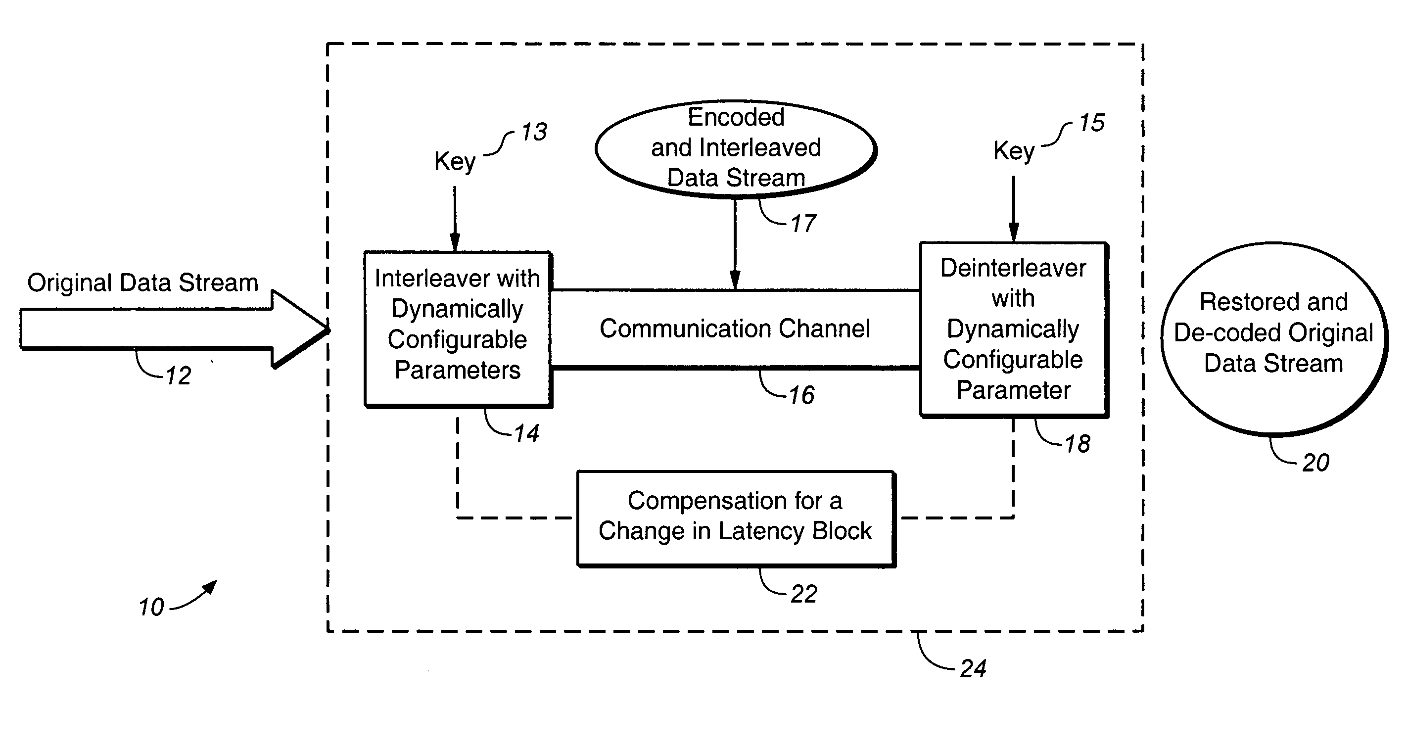
[0020]In one embodiment of the present invention, the step (B) further comprises: (B1) using an anticipator block in the interleaver to compensate for latency decrease caused by at least one dynamically changeable interleaving parameter.
[0022]In one embodiment of the present invention, the step (C) further comprises: (C1) using an anticipator block in the de-interleaver to compensate for latency decrease caused by at least one dynamically changeable interleaving parameter.
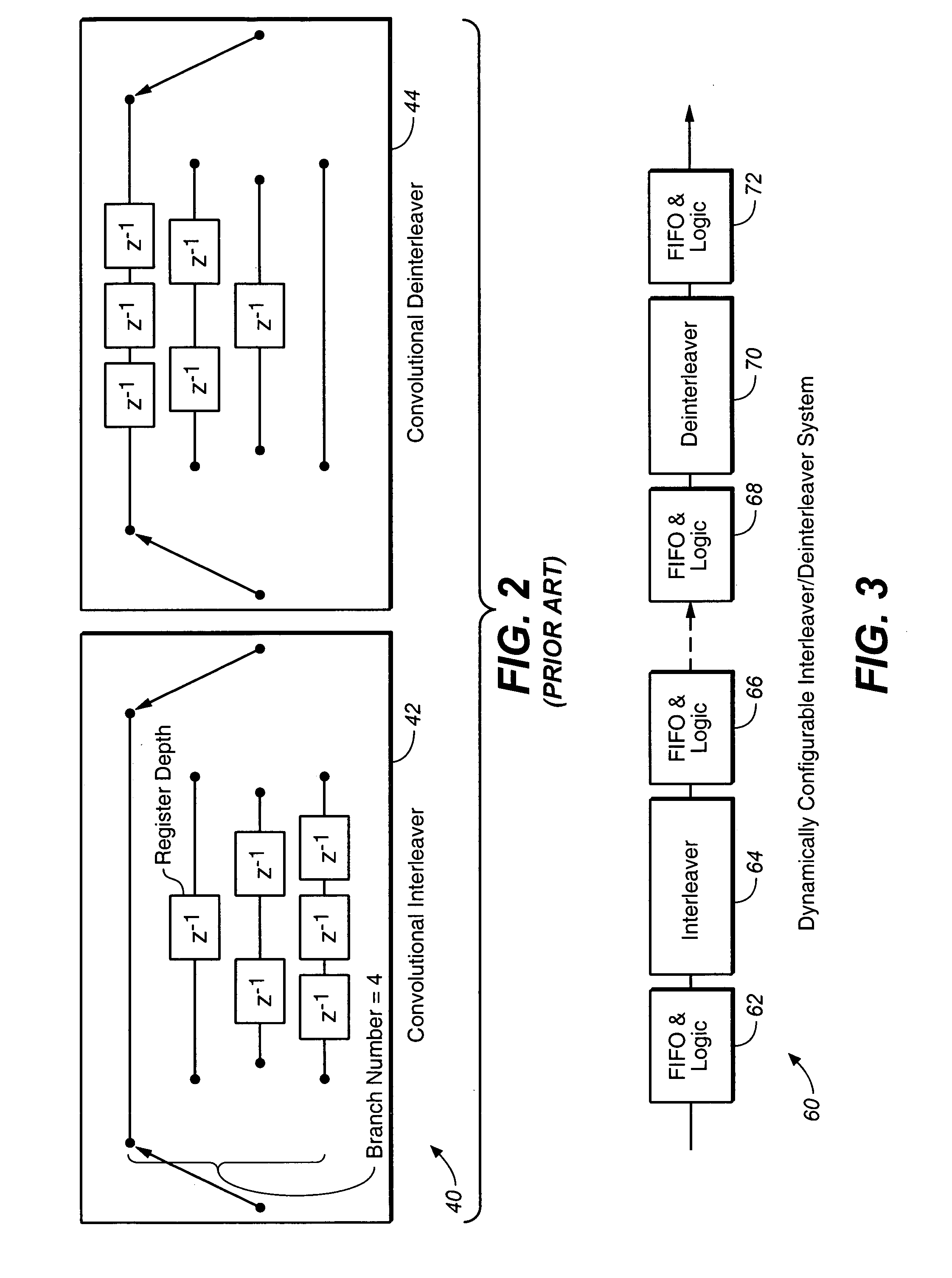
[0026]In this embodiment of the present invention, at least one interleaving parameter is being dynamically changed during data transmission through a communication channel according to the key-algorithm. In this embodiment of the present invention, at least one dynamically changeable interleaving parameter is selected from the group consisting of: {a variable branch number; and a variable register depth}, wherein the variable branch number is a first interleaving parameter being dynamically changed during data transmission through the communication channel, and wherein the variable register depth is a second interleaving parameter being dynamically changed during data transmission through the communication channel. In this embodiment of the present invention, the interleaver is configured to interleave the original data stream, and wherein the interleaved data stream propagates through the communication channel. In this embodiment of the present invention, the interleaver compensates for a change in latency caused by changes in each dynamically changeable interleaving parameter. In this embodiment of the present invention, the de-interleaver is configured to recover the original stream of data. In this embodiment of the present invention, the de-interleaver compensates for a change in latency caused by at least one dynamically changeable interleaving parameter.

Problems solved by technology

Depending on the nature of the generator polynomial, the encountered error may or may not be correctable.

Method used


Image

  • Dynamically configurable interleaver scheme using at least one dynamically changeable interleaving parameter
  • Dynamically configurable interleaver scheme using at least one dynamically changeable interleaving parameter
  • Dynamically configurable interleaver scheme using at least one dynamically changeable interleaving parameter

Examples


Embodiment Construction

.

[0062]Reference will now be made in detail to the preferred embodiments of the invention, examples of which are illustrated in the accompanying drawings. While the invention will be described in conjunction with the preferred embodiments, it will be understood that they are not intended to limit the invention to these embodiments. On the contrary, the invention is intended to cover alternatives, modifications and equivalents that may be included within the spirit and scope of the invention as defined by the appended claims. Furthermore, in the following detailed description of the present invention, numerous specific details are set forth in order to provide a thorough understanding of the present invention. However, it will be obvious to one of ordinary skill in the art that the present invention may be practiced without these specific details. In other instances, well known methods, procedures, components, and circuits have not been described in detail as not to unnecessarily obs...


PUM


Abstract

A method for encrypting and decrypting an original data stream comprising: (A) transmitting a copy of a key to an interleaver and to a de-interleaver, wherein the key includes a key-algorithm configured to describe an evolution in time of at least one interleaving parameter; (B) interleaving the original data stream by using the interleaver, wherein the interleaver compensates for a change in latency caused by at least one dynamically changeable interleaving parameter; and (C) recovering the original data stream from the interleaved data stream propagated through the communication channel by using the de-interleaver adapted to communicate with the communication channel, wherein the de-interleaver compensates for a change in latency caused by at least one dynamically changeable interleaving parameter.

Description

[0001]This is a continuation-in-part of the U.S. patent application Ser. No. 10 / 846,056, entitled: “DYNAMICALLY CONFIGURABLE INTERLEAVER SCHEME”, and filed on May 15, 2004, which is a continuation-in-part of the U. S. patent application Ser. No. 09 / 663,273, entitled: “OPTIMIZED RAM REPRESENTATION OF CONVOLUTIONAL INTERLEAVER / DE-INTERLEAVER DATA STRUCTURE”, and filed on Sep. 18, 2000.BACKGROUND OF THE INVENTION[0002]1. Field of the Invention[0003]This invention relates to the art of electronic data transmission, and more specifically, to a method and apparatus employing a dynamically configurable interleaver scheme.[0004]2. Discussion of the Background Art[0005]Error correction and error detection codes have been used extensively in data communication and data storage applications. In a data communication application, data is encoded prior to transmission, and decoded at the receiver. In a data storage application, data is encoded when stored in a storage device, e.g. in a disk drive...

Claims


Application Information

Patent Timeline
IPC IPC(8): G06F11/07
CPCG11B20/00086H03M13/2732H03M13/6508H04L1/0018H04L1/0041H04L1/0045H04L1/0071
Inventor FLYNN, JAMES P.TANKHILEVICH, BORIS G.
Owner REMEC BROADBAND WIRELESS NETWORKS LLC
Why Eureka
Eureka Blog
Learn More