

System and method for static analysis using fault paths
a fault path and static analysis technology, applied in the evaluation field of programs, can solve problems such as increased false negatives, increased reporting of false negatives, and increased scalability
- Summary
- Abstract
- Description
- Claims
- Application Information
AI Technical Summary
Benefits of technology
Problems solved by technology
Method used
Image

Examples
Embodiment Construction
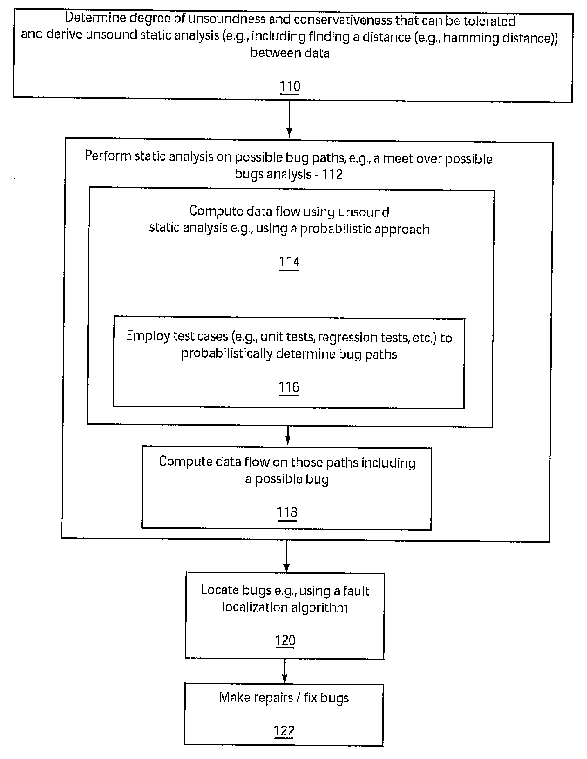
[0027]Embodiments of the present invention determine soundness and conservativeness of programs and access their impact on static program analysis. In a particularly useful embodiment, failed test cases are employed to determine possible bug paths within a program. These bug paths are then employed for computing data flow information for the program. The systems and methods disclosed herein may be employed to more efficiently determine bugs and defects in software programs.
[0028]Embodiments of the present invention can take the form of an entirely hardware embodiment, an entirely software embodiment or an embodiment including both hardware and software elements. In a preferred embodiment, the present invention is implemented in software, which includes but is not limited to firmware, resident software, microcode, etc.
[0029]Furthermore, the present invention can take the form of a computer program product accessible from a computer-usable or computer-readable medium providing program...
PUM
 Abstract
Description
Claims
Application Information