Faucet With Spray Head

Active Publication Date: 2008-11-13
KOHLER CO
View PDF28 Cites 41 Cited by
  • Summary
  • Abstract
  • Description
  • Claims
  • Application Information

AI Technical Summary

Benefits of technology

[0014]The present invention has, in various embodiments, various advantages. For example, one embodiment will provide a compact configuration for the outer housing adjacent the linkage between the control valve and inlet and outlet lines. Another embodiment provides a decorative handle exterior, while still providing set screw access. Still another embodiment can provide positive s

Problems solved by technology

This required the outer housing to bulge in order to accommodate the elbow plus the other relevant connections, and thus created design constraints.
In another aspect of known faucets with spray heads/handles, prior designs included a control handle with an exposed set screw which could be inadvertently loosened or corroded by water, and/or reduced the aesthetic appeal of the handle.
Some of these handles were also formed with an unsightly visible cuta

Method used


Image

  • Faucet With Spray Head
  • Faucet With Spray Head
  • Faucet With Spray Head

Examples


Example

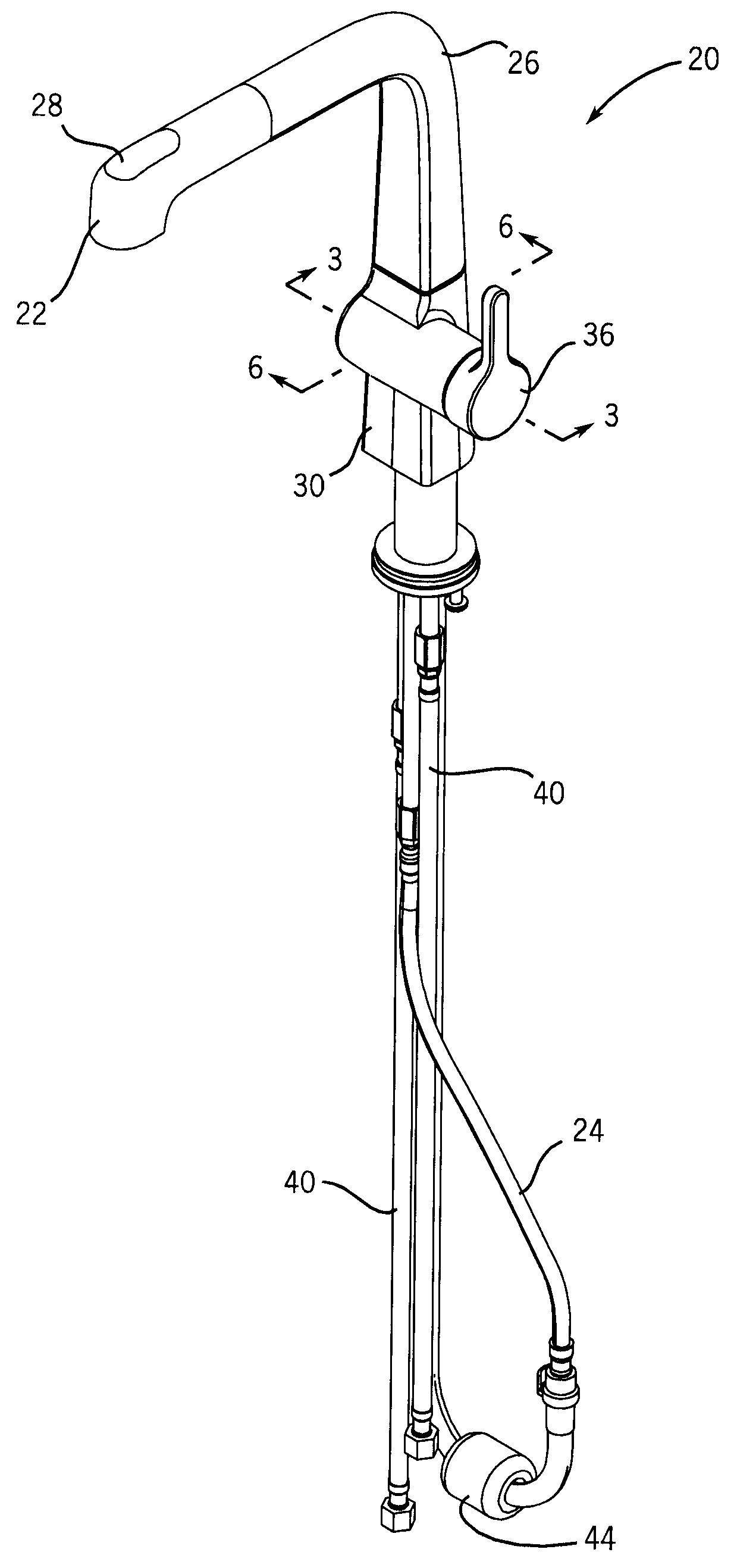
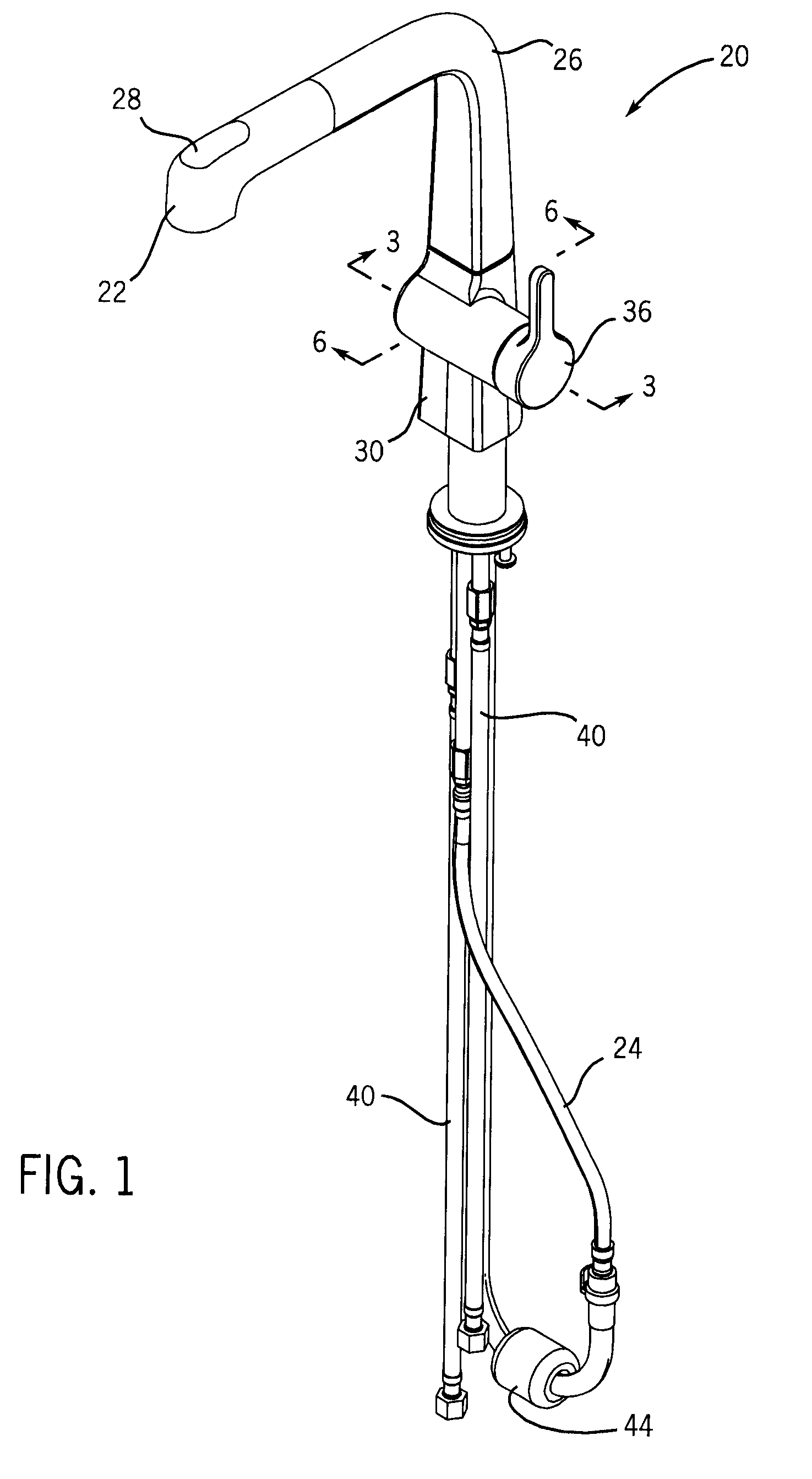
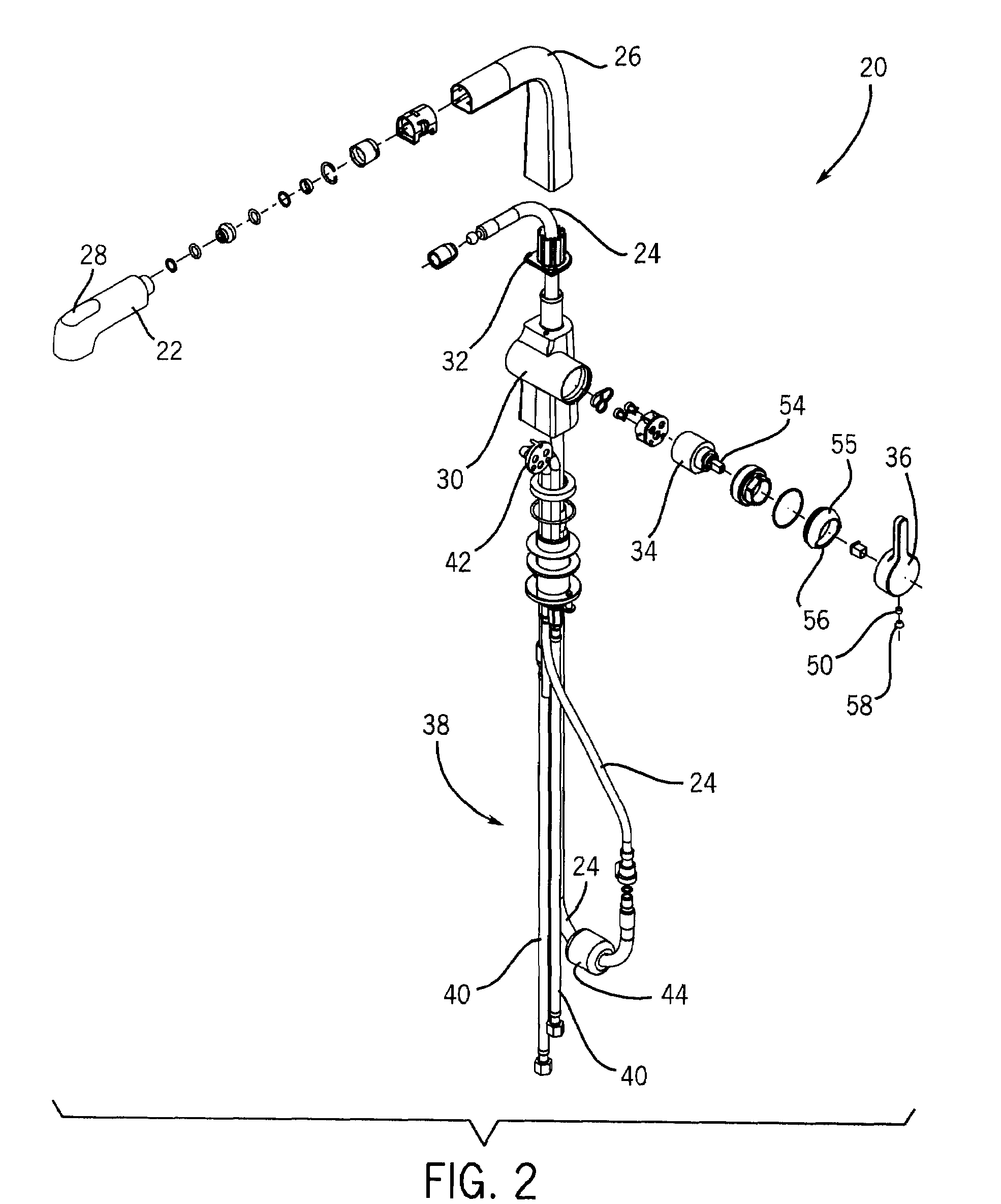
[0032]Referring now to the drawings, and more particularly first to FIGS. 1, 2 and 11, there is shown a faucet assembly 20 which includes spray head 22 connected to a flexible outlet line 24 which is routed through spray head harbor 26. Spray head 22 may optionally include a spray control pushbutton 28, and may also include other controls. Spray head harbor 26 is connected to valve housing 30 via bearing 32.

[0033]Mixing valve 34 is connected to control handle 36, as also shown in FIGS. 3 and 4. Tilting and / or rotation of control handle 36 determines the combination of hot and cold water and / or the volume of water available to spray head 22 via flexible outlet line 24. The valve used for this purpose may be any of a number of conventional mixing valves.

[0034]Inlet / outlet assembly 38 (see particularly FIGS. 2,5 and 12-14) is in fluid communication with mixing valve 34. The inlet / outlet assembly 38 has inlet lines 40 and outlet line 24 permanently affixed to a face plate 42 as by casti...


PUM


Abstract

Disclosed is a swivel faucet, such as one having a pull-out sprayer. In one aspect the inlet and outlet lines are formed in an integral structure with a transverse plate that faces a mixing valve. In another aspect the control handle for the faucet is provided with a concentric visible bore and hidden set screw bore combined with a bushing having a cutout to facilitate their use. In still another aspect there is provided a bearing that mounts to a pivotable sprayer and provides distinct swivel positions through the use of a detent connection to a land.

Description

CROSS-REFERENCE TO RELATED APPLICATIONS[0001]This application claims priority based on U.S. provisional application 60 / 916,338, which was filed May 7, 2007.STATEMENT OF FEDERALLY SPONSORED RESEARCH OR DEVELOPMENT[0002]Not applicable.BACKGROUND OF THE INVENTION[0003]This invention relates generally to faucets with spray heads. More particularly it relates to such a faucet in which there is a pull-out sprayer mounted on a swivelable harbor.[0004]In one aspect of known faucets with spray heads / handles, prior designs (e.g. as shown in U.S. Pat. No. 6,757,921) include a separate elbow which is linked at its lower end to inlet hot and cold lines and an outlet line, and to a mixing valve at its vertical side which is connected to an actuation handle. This required the outer housing to bulge in order to accommodate the elbow plus the other relevant connections, and thus created design constraints. It is desirable to have a more compact assembly for connecting the inlet and outlet lines to a...

Claims


Application Information

Patent Timeline
IPC IPC(8): E03C1/04F16K11/078B05B1/16
CPCE03C1/04E03C2001/0415E03C1/0403E03C1/0412F16K19/006Y10T137/86815Y10T137/9464
Inventor BARES, WILLIAM R.ERICKSON, PERRY D.
Owner KOHLER CO
Why Eureka
Try Eureka