Eureka AIR delivers breakthrough ideas for toughest innovation challenges, trusted by R&D personnel around the world.

Power generation device using lift type oscillating hydrofoils to capture tidal current energy

A power generation device, a lifting technology, applied in the directions of ocean energy power generation, engine components, machines/engines, etc., can solve the problem that the system cannot complete the quasi-sinusoidal heave-pitch coupled motion, the pitch amplitude deviates from 90 degrees, and gets stuck in one position, etc. problems, to facilitate large-scale commercial operation, to eliminate the unequal gravity and buoyancy, and to work reliably

Inactive Publication Date: 2013-12-25
SHANDONG UNIV
View PDF5 Cites 13 Cited by
  • Summary
  • Abstract
  • Description
  • Claims
  • Application Information

AI Technical Summary

Problems solved by technology

When the incoming flow velocity is low, the incoming flow is instantaneously unstable, and the gravity of the hydrofoil sinking system is greater than or equal to the buoyancy and lift, the system may not be able to complete the complete quasi-sinusoidal sinking-pitching coupling motion, and may be stuck in one position In addition, the scheme requires that the pitch phase difference of the two hydrofoils is 90 degrees. In fact, due to the serious leakage in the swing cylinder, the long-term operation will inevitably deviate from the pitch amplitude of 90 degrees, which will cause the system to fail.

Method used


Image

  • Power generation device using lift type oscillating hydrofoils to capture tidal current energy
  • Power generation device using lift type oscillating hydrofoils to capture tidal current energy
  • Power generation device using lift type oscillating hydrofoils to capture tidal current energy

Examples


Embodiment Construction

[0022] Below in conjunction with the accompanying drawings, the specific implementation of the lifting type oscillating hydrofoil capture tidal current energy generating device of the present invention is described in detail as follows:

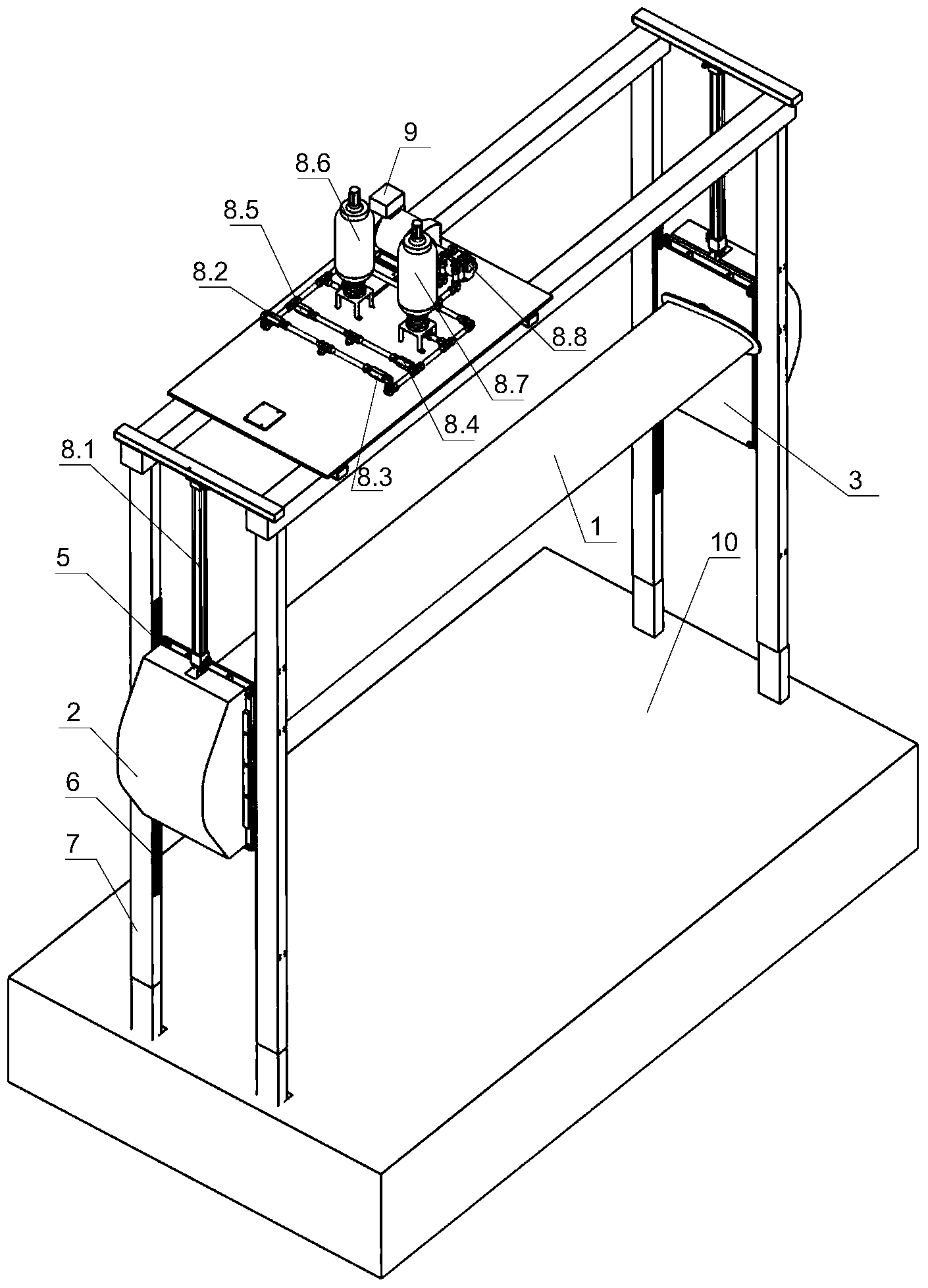
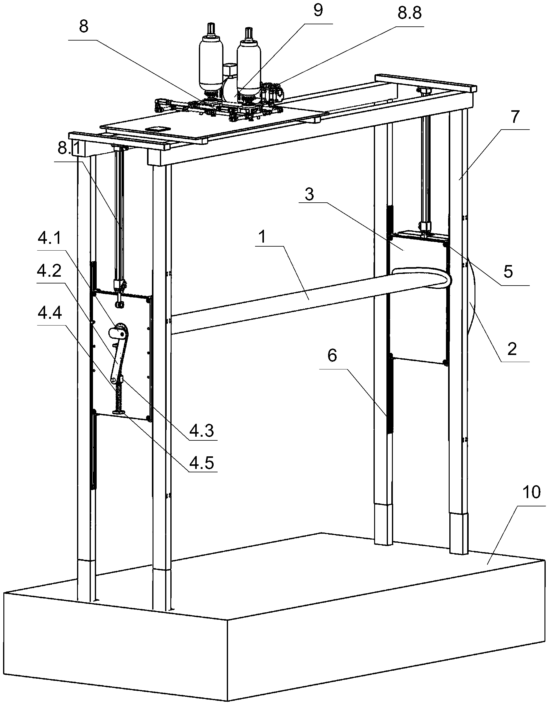
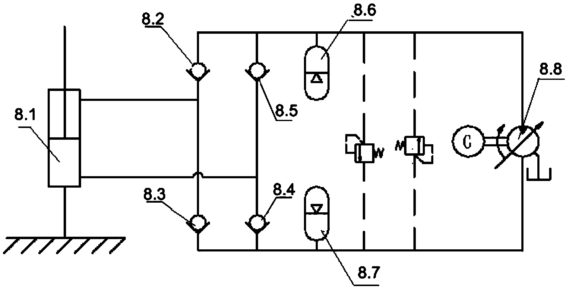
[0023] as attached figure 1 , figure 2 , image 3 As shown, the lifting type oscillating hydrofoil of the present invention captures tidal current energy generating device, and it comprises hydrofoil 1, buoyancy box 2, hydrofoil support frame 3, hydrofoil pose adjustment system, pulley 5, guide rail 16, support 7, hydraulic pressure Type energy conversion system 8, generator 9, working platform 10, etc. The hydrofoil 1 and the buoyancy box 2 are installed on the hydrofoil support frame 3, and the hydrofoil posture adjustment system is installed inside the buoyancy box 2, and the pulley 5 is installed on the hydrofoil support frame 3, and the pulley 5 can move along the guide rail 16, and the guide rail 6 Installed on the bracket 7, the hy...


PUM


Abstract

The invention particularly discloses a power generation device using lift type oscillating hydrofoils to capture tidal current energy, which comprises a working platform and hydrofoils, wherein the top of the working platform is provided with a bracket connected with the working platform; both ends of each hydrofoil are mounted on a hydrofoil supporting frame which can slide back and forth along the bracket in the perpendicular direction; a floating tank is mounted on the lateral surface of the hydrofoil supporting frame; a hydrofoil position / attitude regulation system is mounted between the water tank and the hydrofoil supporting frame; the hydrofoils are connected with a hydraulic energy conversion system; and the hydraulic energy conversion system sends converted energy to a generator. By using the tidal current energy power generation device, the set can be arranged in a relatively shallow water area. The number of the hydrofoils can be regulated according to water depth, and high energy capture rate can be obtained under working conditions of high flow rate and low flow rate; the structure is simple, reliable and stable; and self start and self oscillation maintenance can be realized under the action of fluid. Thus, the power generation device has wide expected application prospects.

Description

[0001] technical field [0002] The invention relates to a device suitable for capturing tidal (ocean) current energy for power generation, which belongs to the field of mechanical manufacturing. Background technique [0003] Energy is the basic element for human survival and all activities. Throughout the development of today's society, human development is increasingly dependent on energy. With the extensive use of fossil energy, environmental pollution is becoming more and more serious. In order to reduce the national economy The development depends on fossil fuels. Under the guidance of the policies of the governments of various countries, the development and application of renewable energy utilization equipment have grown rapidly. Tidal (ocean) current energy has been valued by national and provincial planning departments. [0004] The research on hydrodynamic power generation technology in all countries in the world started relatively late, but has developed rapidly i...

Claims


Application Information

Patent Timeline
IPC IPC(8): F03B13/26
CPCY02E10/30
Inventor 王勇逯建伟谢玉东王龙晖李建辉孙华宵
Owner SHANDONG UNIV
Why Eureka
Eureka Blog
Learn More