Boiler plant, a support structure and a method for supporting the walls of a steam boiler of a boiler plant

Inactive Publication Date: 2008-11-13
METSO POWER OY
View PDF11 Cites 9 Cited by
  • Summary
  • Abstract
  • Description
  • Claims
  • Application Information

AI Technical Summary

Benefits of technology

[0003]Now a solution has been invented for a combined horizontal support system of a boiler and a boiler building for supporting the walls of a boiler without heavy ring st

Problems solved by technology

Thus, a great deal of steel is needed

Method used


Image

  • Boiler plant, a support structure and a method for supporting the walls of a steam boiler of a boiler plant
  • Boiler plant, a support structure and a method for supporting the walls of a steam boiler of a boiler plant
  • Boiler plant, a support structure and a method for supporting the walls of a steam boiler of a boiler plant

Examples


Embodiment Construction

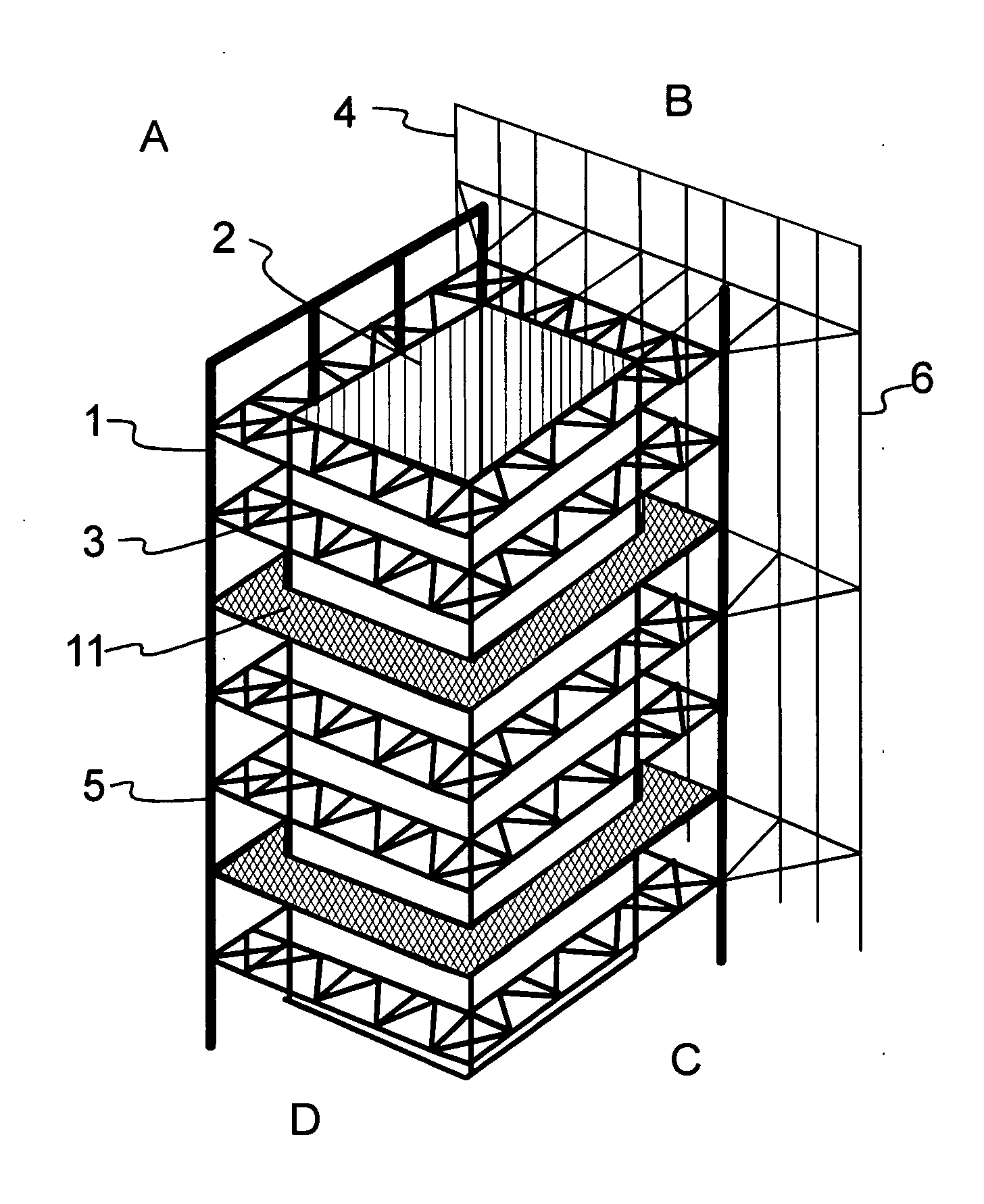
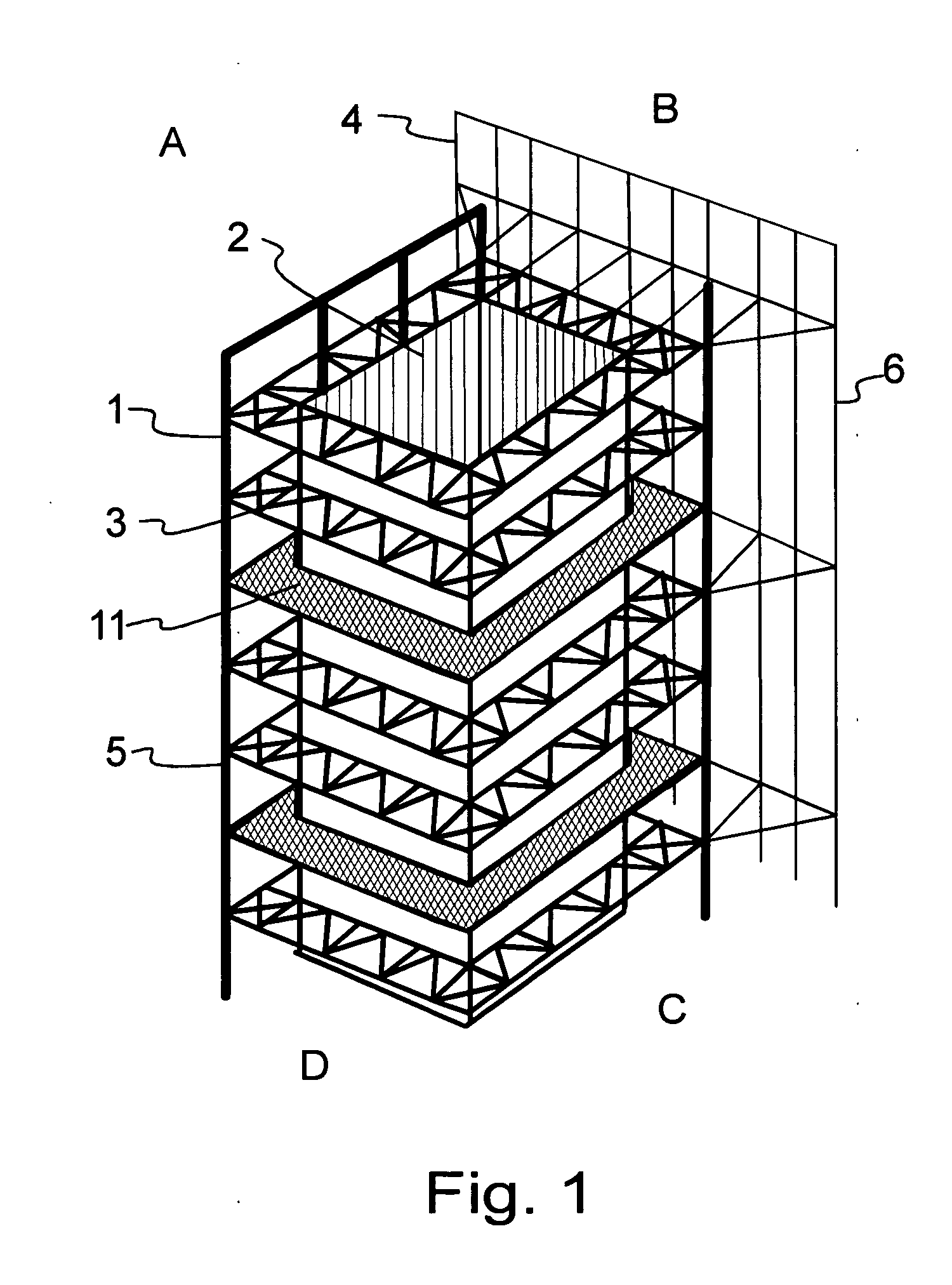
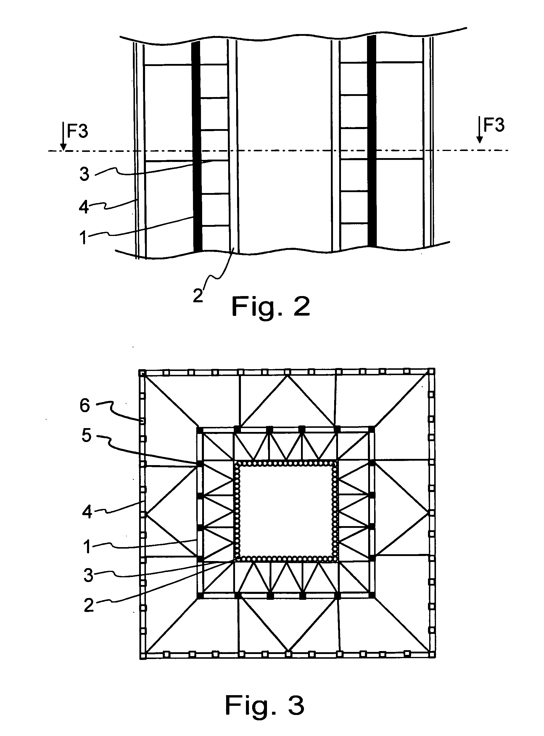
[0026]FIG. 1 shows only those parts of a boiler plant that are necessary for describing the invention. These are the frame 1 of a boiler house, a boiler 2 and a support structure 3. In addition, other structures are required in the boiler plant, inter alia for supplying fuel and air, and for processing flue gases. In addition, there are often different structures for use and maintenance work. In FIG. 1 the frame 1 of the boiler plant is for clarity shown only on one side, i.e. side A, even though the frame in practice is on each side. Correspondingly, the support structure 4 of an outer screen is shown only on side B of the boiler house, even though such a frame is advantageously on every screened side. Sides C and D of the boiler house do not show the frame 1 of the boiler house, nor the screening frame 4, in order to shown the location of the support structures 3 more clearly. The frame 1 of the boiler house comprises vertical boiler columns 5. The screening frame 4 comprises vert...


PUM


Abstract

A boiler plant, which comprises a boiler (2) and a frame (1) of a boiler house surrounding the boiler. In addition, the boiler plant comprises support structures (3), by which the walls of the boiler (2) are supported laterally to the frame (1) of the boiler house. In addition, the invention relates to a support structure (3) and a method for supporting the walls of a boiler (2) of a boiler plant.

Description

FIELD OF THE INVENTION[0001]The invention relates to a boiler plant, a support structure, as well as a method for supporting the walls of a steam boiler.BACKGROUND OF THE INVENTION[0002]The boilers of typical boiler plants comprise tubular walls, where water and / or steam circulates. Combustion takes place inside the boiler in a furnace, and as a result of the combustion and gas flows negative pressures and positive pressures may occur in different areas of the boiler. The pressure effect is directed at the walls of the boiler and the walls tend to move. For this reason, different support structures are made in the walls. Typically a support structure is a horizontal buckstay, which circles the outer wall of the boiler. Typically the support ring is formed of a strong steel beam, which is attached to the wall of the boiler in a suitable manner. One known support structure solution is disclosed in U.S. Pat. No. 5,557,901. The boilers of large boiler plants may be several tens of meter...

Claims


Application Information

Patent Timeline
IPC IPC(8): F22B37/24
CPCF22B37/24F22B37/208F22B37/20
Inventor SEPPANEN, MARTTIRUOTSALA, JOHAN
Owner METSO POWER OY
Why Eureka
Try Eureka