Boiler waste heat gradient utilization and deep water heat recovery system based on absorption heat pump

An absorption heat pump and boiler waste heat technology, applied in heat recovery systems, heating systems, heat pumps, etc., can solve the problems of lack of research and application, and achieve the effects of saving water resources, reducing environmental impact, and enhancing heating capacity

Active Publication Date: 2021-06-22
CHINA COAL RES INST CCRI ENERGY SAVING TECH CO LTD
View PDF6 Cites 4 Cited by
  • Summary
  • Abstract
  • Description
  • Claims
  • Application Information

AI Technical Summary

Problems solved by technology

However, at present, absorption heat pump technology is commonly used in coal-fired power plants and gas-fired industrial boilers, and there is a lack of relevant research and application in the field of pulverized coal industrial boilers.

Method used


Image

  • Boiler waste heat gradient utilization and deep water heat recovery system based on absorption heat pump
  • Boiler waste heat gradient utilization and deep water heat recovery system based on absorption heat pump

Examples


Embodiment 1

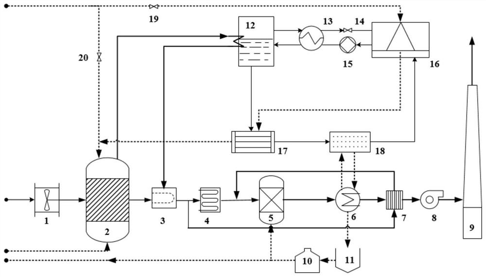
[0037] The absorption heat pump in this embodiment is single effect. Such as figure 1 As shown, the absorption heat pump is composed of a generator 12, a solution exchanger 13, a solution pump 15, a throttle valve 14, an absorber 16, a condenser 17, an evaporator 18 and connecting pipes. The blower 1 is connected to the boiler 2, and the flue gas generated by the boiler 2 is divided into two parts, one part of the flue gas enters the generator 12, and the other part of the flue gas enters the denitrification device 3. The flue gas flowing out from the denitration device 3 is divided into two parts, one part enters the low-temperature heating surface 4 and then enters the desulfurization device 5, and the other part enters the reheater 7, and then enters the desulfurization device 5 after exothermic cooling. After the desulfurization device enters the heat exchanger 6 to condense and release heat to form low-humidity dry flue gas, the high-temperature flue gas realizes double ...

Embodiment 2

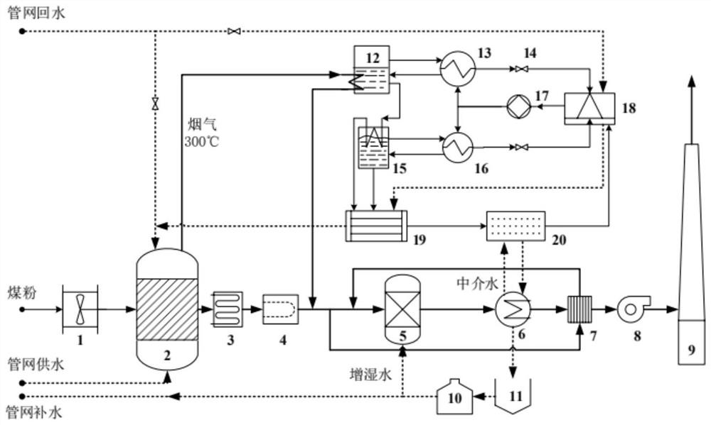
[0041] The absorption heat pump in this embodiment is double-effect. Such as figure 2 As shown, the absorption heat pump consists of a high-pressure generator 12, a high-temperature solution exchanger 13, a low-pressure generator 15, a low-temperature solution exchanger 16, a solution pump 17, a throttle valve 14, an absorber 18, a condenser 19, an evaporator 20 and Connecting pipes. The blower 1 is connected to the boiler 2, and the flue gas generated by the boiler 2 is divided into two parts, one part of the flue gas enters the high-pressure generator 12, and the other part of the flue gas enters the denitrification device 3. The flue gas flowing out from the denitrification device 3 is divided into two parts, one part enters the low-temperature heating surface 4 and then enters the desulfurization device 5, and the other part enters the reheater 7, and then enters the desulfurization device 5 after exothermic cooling. After the desulfurization device enters the heat exch...


PUM


Abstract

The invention discloses a boiler waste heat gradient utilization and deep water heat recovery system based on an absorption heat pump. The embedded absorption heat pump is used for deeply recycling waste heat and water of a low-temperature flue gas with a high moisture content, the recycled flue gas waste heat is used for heating heat supply network return water to supply heat, the recycled water resource is used for supplementing heat supply network pipe water and boiler feed water, and therefore deep recycling of the low-temperature flue gas waste heat and the water resource is achieved. The problems of metal corrosion, low-temperature cold source preparation and the like in the field of flue gas waste heat recovery can be effectively solved, and water resources are effectively saved. In the heating season, the flue gas waste heat can be used for gradient heating of the heat supply network return water, the heat supply capacity of the boiler is effectively enhanced, energy consumption is reduced, the energy utilization efficiency is improved, the environmental influence of a boiler plant is reduced, and considerable economic benefits and environmental benefits are achieved.

Description

technical field [0001] The invention belongs to the field of energy conservation and environmental protection, and in particular relates to a cascade utilization of boiler waste heat and a deep water heat recovery system based on an absorption heat pump. Background technique [0002] At present, the high-efficiency pulverized coal industrial boiler system has significant advantages such as high combustion efficiency, instant start and stop, and strong operability, and has been widely used in the steam supply and heating industry. Its exhaust fume contains SO 2 Such as acid gas and dust, usually using semi-dry desulfurization technology (high rate ash calcium circulation flue gas desulfurization technology) or wet desulfurization technology, which can effectively remove harmful gases and dust to meet ultra-low emission standards. The water vapor content in the treated flue gas is as high as 20%, and contains a large amount of sensible heat, latent heat and water resources. W...

Claims


Application Information

Patent Timeline
Patent Type & Authority Applications(China)
IPC IPC(8): F25B30/04F25B41/40F25B41/20F25B33/00F25B37/00F24D15/04F24D19/00F23J15/02F23L15/00F28B9/08
CPCF25B30/04F25B33/00F25B37/00F24D15/04F24D19/00F23J15/022F23L15/00F28B9/08Y02A30/27Y02E20/34Y02B30/62Y02B30/52
Inventor 李美军张鑫王乃继王永英李慧崔豫泓程鹏杨石程晓磊段璐陈隆刘振宇孟长芳王志强李婷魏琰荣龚艳艳戈铁柱闫黎黎曹好白一飞潘昊邢文朝
Owner CHINA COAL RES INST CCRI ENERGY SAVING TECH CO LTD
Why Eureka
Try Eureka