
Boiler arrangement

A boiler and back wall technology, applied in the field of expansion boiler installation, can solve problems such as unachievable results, achieve the effect of reducing initial investment and maintenance work, and shortening the time when the boiler stops working

Inactive Publication Date: 2007-09-26
ANDRITZ AG
View PDF1 Cites 4 Cited by
  • Summary
  • Abstract
  • Description
  • Claims
  • Application Information

AI Technical Summary

Problems solved by technology

In this case, the best results cannot be achieved taking into account the combustion process in the boiler

Method used


Image

  • Boiler arrangement

Examples


Embodiment Construction

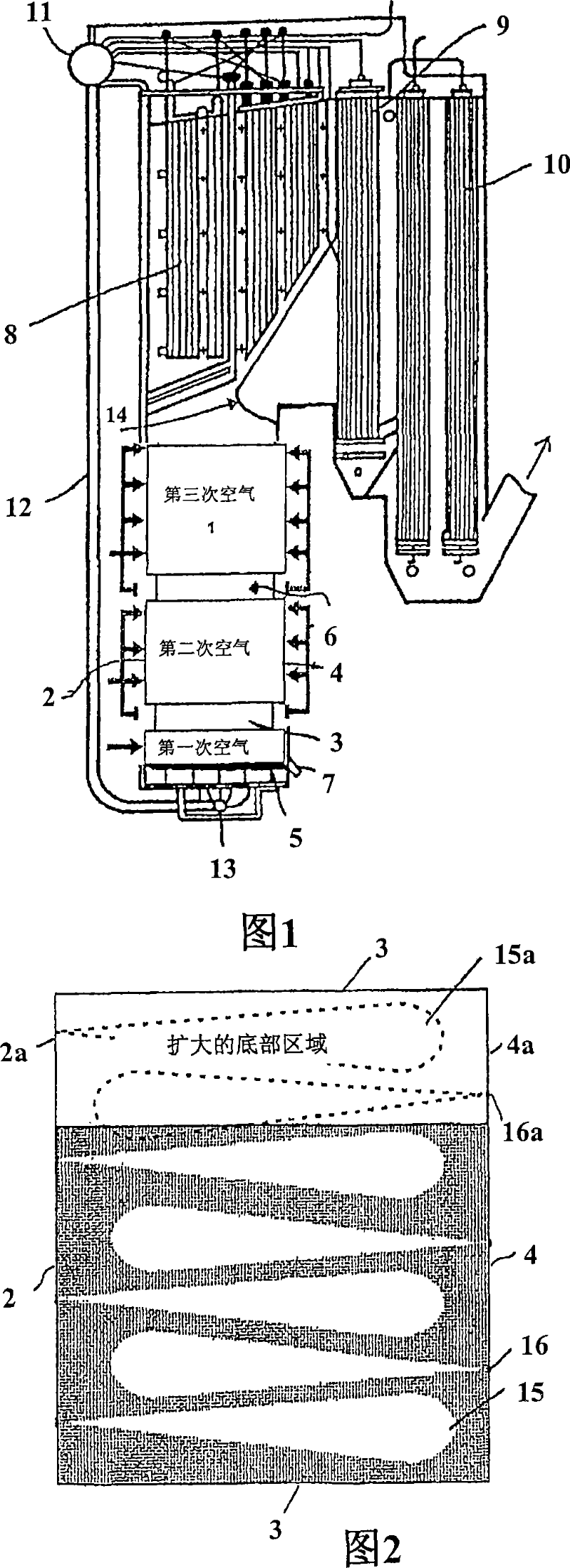
[0023] Figure 1 schematically shows a chemical recovery boiler structure with a furnace 1 defined by the following water tube walls: a front wall 2, two side walls 3 and a rear wall 4 and a bottom wall 5 which also constitutes the water tubes. Combustion air is fed into the furnace from several different heights as first, second and third air. Other air heights are also possible. Waste liquor, such as black liquor, is introduced via nozzles 6 between the second and third air zones. During the combustion process, a molten bed from the effluent is formed in the bottom 5 of the furnace, from where the melt is output via a melt delivery pipe 7 installed in the bottom of the furnace.

[0024] The heat recovery surface of the boiler, i.e. the superheater 8, is located above the furnace, while the rear wall 4 of the furnace accommodates the hot surface along the superheater, boiler tube bundle 9 and economizer 10 in the upper part of the furnace, where the emission of flue gases gen...


PUM


Abstract

The present invention relates to an arrangement and a method for enlarging a boiler, especially a chemical recovery boiler, and in that way for optimizing and simplifying a capacity increase. An object of the present invention is to provide for a boiler plant, which is easily adaptable to increasing boiler loading without decreasing the efficiency of the combustion process, but facilitating its optimal control. In accordance with the invention, the option of enlarging the boiler is taken into account by reserving space in connection with the boiler so that a side wall (3) may be moved, thus increasing the length of the front wall (2) and the rear wall (4). After the enlargement, the distance between the front and rear walls is essentially the same as before the enlargement.

Description

technical field [0001] The present invention relates to an arrangement and method for expanding a boiler, in particular a chemical recovery boiler of a pulp mill, and in particular its furnace, and thus optimizing and simplifying the increase in its capacity. Background technique [0002] The furnace of a chemical recovery boiler for burning black liquor has a front wall, a rear wall and side walls. The black liquor injection device is arranged on the side wall at one level or several levels. Air ports are provided on the side walls at several levels for introducing air into the furnace from an air source. The flue gases produced in the combustion of black liquor are directed into contact with various heat transfer devices, superheaters, boiler tube bundles and boiler water preheaters (economizers), so that the heat present in the gas becomes available in the heat transfer device It is recovered in the form of flowing water, steam or mixtures thereof. A nose structure is ...

Claims


Application Information

Patent Timeline
Patent Type & Authority Applications(China)
IPC IPC(8): F23G7/04F23M5/08D21C11/12F23M20/00
CPCF23G2203/70F23M5/08D21C11/12F23G7/04
Inventor 让·斯托尔巴卡彼得里·蒂卡
Owner ANDRITZ AG
Learn More