Gas Sensor

a gas sensor and sensor technology, applied in the field of electrochemical gas sensors, can solve the problems of reducing reducing or completely canceling affecting the output of sensor components, so as to reduce or completely cancel the effect of interfering stimulus, simple robust solution, and reduce the effect of sensor outpu

Active Publication Date: 2008-11-13
LIFE SAFETY DISTRIBUTION
View PDF4 Cites 16 Cited by
  • Summary
  • Abstract
  • Description
  • Claims
  • Application Information

AI Technical Summary

Benefits of technology

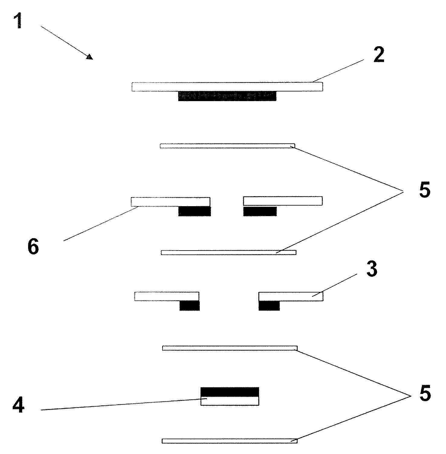
[0024]According to a third aspect of the present invention, an electrochemical sensor for sensing a target gas and generating a sensor output related to the concentration of the target gas, comprises a first gas sensing electrode comprising a first catalyst material reactive to the target gas and which produces a response to an interfering stimulus; a second gas sensing electrode comprising a second catalyst material which produces a response to the interfering stimulus of opposite polarity to the response of the first catalyst material to that interfering stimulus; a counter electrode; an electrolyte with which each of the gas sensing electrodes and the counter electrode are in contact; and means for electronically processing the responses of the first and second gas sensing electrodes to the interfering stimulus, so as to reduce or cancel out the effect on sensor output of the interfering stimulus.
[0025]By adjustment of the relative proportions of the first and second catalyst materials, it is possible to reduce or completely cancel out the effect of an interfering stimulus, whether transient or steady-state, and thereby produce a simple robust solution to the above-described problem.

Problems solved by technology

This may result in damage to sensor components and places more strain on the seals retaining electrolyte within the housing.
There is also a significant risk of the sensor drying out, resulting in a loss of electrolytic contact between the electrodes and hence a malfunction.
If the electrolyte takes on water it becomes more neutral, which may compromise the activity of the system towards the reactions of interest.
In extreme cases, leakage of electrolyte due to pressure build-up may occur.
In the short term, relatively rapid, or transient, changes in ambient conditions (typically on a timescale of a few seconds) may affect the instantaneous output of the sensor rather than its long term performance.
In severe cases, reading errors may temporarily produce a fail-to-danger condition by offsetting the true response to a target measurand (although this is usually very short-lived).
A more common problem is that the instrument is put into an alarm condition by the very rapid change in output it experiences.
False alarms are very undesirable since they may lead to unwarranted interruptions in operation of the plant and cause a loss of confidence in the instrument.
The severity of such effects is more marked in some electrochemical systems than others and can be particularly troublesome in sensors with inherently low sensitivity, since in such cases a comparatively small shift in output current is interpreted as a relatively high gas concentration.
For example, sensors for ppm-level detection of chlorine and hydrogen chloride employing graphite catalysts are particularly prone to humidity transient problems.
Other potential applications are more challenging.
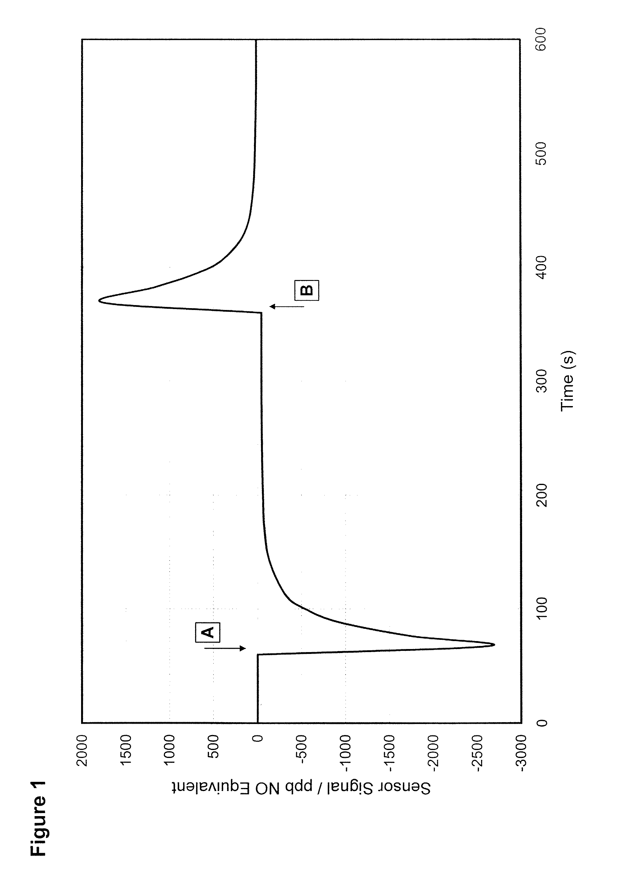
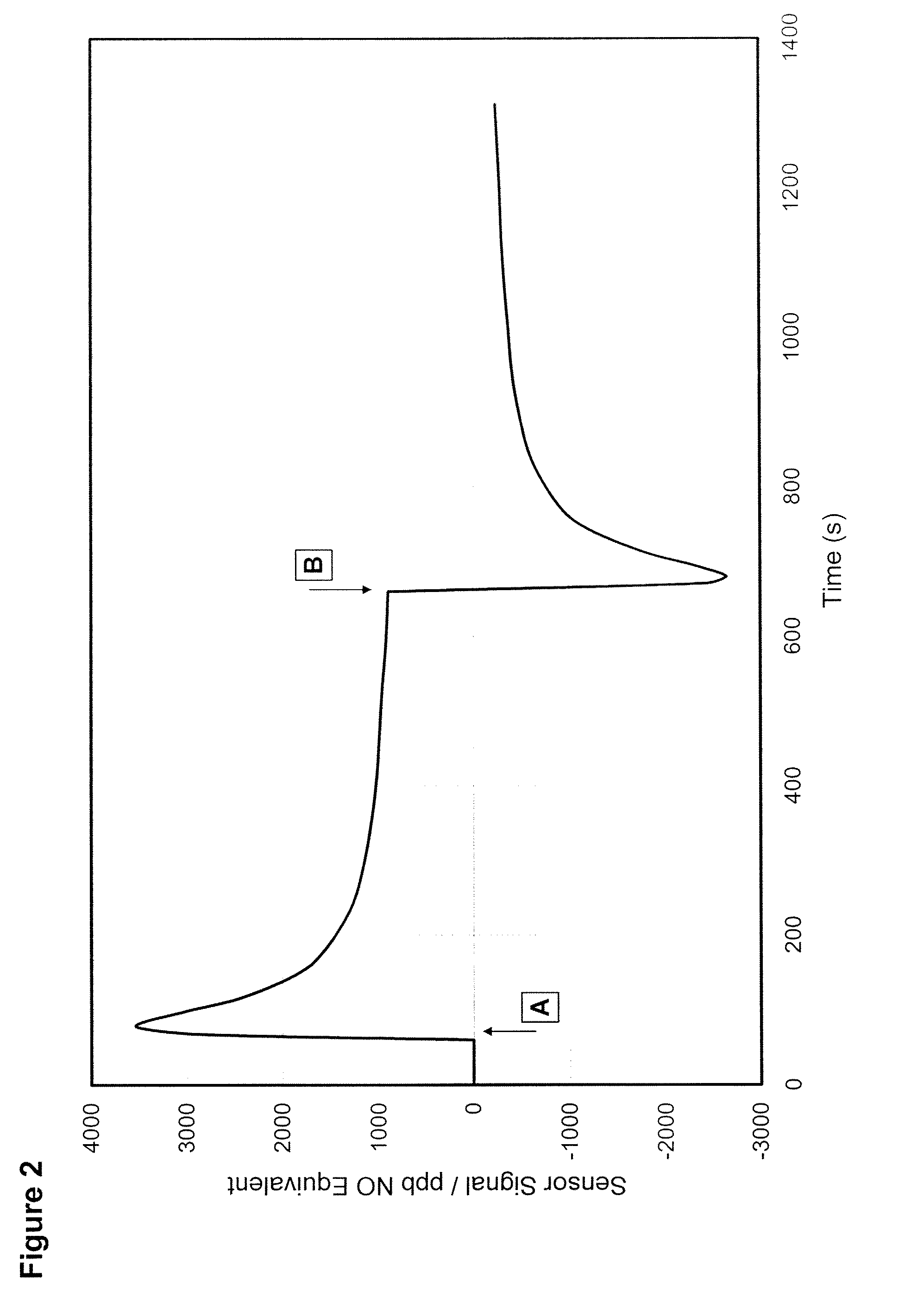
This represents a severe difficulty when the typical level of NO in exhaled breath for a healthy subject is ˜15 ppb, but is present in a background whose humidity content can reach 100% RH and varies rapidly with time.
However, there is currently no viable, low cost, maintenance-free way of achieving the same result in personal monitors.
Thus, a simple solution applicable across a wide range of devices throughout their operating life is unlikely to be achieved in this way.
However, most gases show high activity on comparatively few catalysts, and so the practical options are quite limited.
This often means that a compromise must be made in respect of other undesirable effects, such as cross-sensitivity.
Whilst both methods work adequately for steady-state interferences, they are relatively complex to implement, requiring additional components and changes to the usual sensor hardware.
They also tend to be less effective in cases where transient behaviour is involved, due to the difficulty in matching the speed of response of the two electrodes.

Method used


Image

  • Gas Sensor
  • Gas Sensor
  • Gas Sensor

Examples


example

[0070]In the following, all references to % are to %Xo by weight unless indicated to the contrary.

[0071]32.3 g of Type 4 Synthetic Graphite (available from Johnson Matthey), having a surface area of 5 to 20 m2 / g and a median (D50) particle size (by volume) in the range 15 to 25 μm and 1.00 g of Ruthenium Black (99.9% metals basis, available from Alfa Aesar, Germany), were milled together in a Turbula T2F mixing machine (available from Willy A. Bachofen AG) for 20 minutes at a mixing speed of 100 cycles / min., to form an homogeneous mixture of the two catalyst materials. The resulting catalyst mixture contained 97 weight % graphite and 3 weight % ruthenium black.

[0072]A liquid mixture was obtained by mixing together in a beaker 0.080 ml of 35% ammonia solution, 21 ml PTFE dispersion (60% PTFE, 6% Triton-X dispersant, 34% water) and 12 g of 1% polyacrylic acid solution. The catalyst mixture was added in small amounts to the liquid mixture and mixed until the powder was wetted and an ho...


PUM

PropertyMeasurementUnit
RHaaaaaaaaaa
humidityaaaaaaaaaa
humidityaaaaaaaaaa

Abstract

The present invention provides a unique solution to the problems of both steady-state and transient signals produced by a variety of interfering stimuli, including humidity, which relies upon the inclusion in a gas sensing electrode in an electrochemical gas sensor of a catalyst material in addition to a first catalyst material reactive to the target gas, the additional, or second, catalyst material producing a response to an interfering stimulus which is of the opposite polarity to that generated by the first catalyst material.

Description

FIELD OF THE INVENTION[0001]The present invention relates to electrochemical gas sensors having reduced sensitivity to interfering stimuli, in particular humidity.BACKGROUND TO THE INVENTION[0002]Electrochemical gas sensors operate on fuel cell principles, in that the gas or vapour to be sensed is caused to react at an electrode of an electrochemical cell, thereby generating a current which is a function of the concentration of the gas or vapour to be sensed.[0003]Electrochemical gas sensors are widely used for the detection of toxic gases in a variety of applications. These include measurements in industrial environments for personal protection; combustion emission monitoring from fixed and mobile sources to minimise environmental impact and maximise fuel efficiency; monitoring discharges from fixed plant for regulatory certification; and medical applications. Electrochemical gas sensors based on liquid electrolytes and gas diffusion electrodes, typically employing gas diffusion ba...

Claims


Application Information

Patent Timeline
Patent Type & Authority Applications(United States)
IPC IPC(8): G01F1/64B01J21/18G01N27/26C09D1/00
CPCB01J21/18B01J23/44B01J23/462B01J37/0036G01N27/4045
Inventor JONES, MARTIN
Owner LIFE SAFETY DISTRIBUTION
Why Eureka
Try Eureka