Method for charging a battery of an autonomous system

a technology of autonomous systems and charging methods, applied in the direction of secondary cell charging/discharging, electric vehicles, electrical apparatus, etc., can solve the problems of excessive overcharging of batteries, non-optimized end of charging criteria, and insufficient battery charging. achieve the effect of optimizing the battery charging process, limiting internal degradation phenomena, and preserving optimum safety

Inactive Publication Date: 2008-11-13
COMMISSARIAT A LENERGIE ATOMIQUE ET AUX ENERGIES ALTERNATIVES
View PDF22 Cites 46 Cited by
  • Summary
  • Abstract
  • Description
  • Claims
  • Application Information

AI Technical Summary

Benefits of technology

[0014]The object of the invention consists in palliating the above-mentioned shortcomings and in particular in optimizing

Problems solved by technology

However, calculation of the energy delivered to the battery remains imprecise and the end of charging criterion remains non optimized.
In most cases, this imprecision leads to excessive overcharging of the battery and, in the case of the lead technology, to a large water consumption and to corrosion of the grids.
This presents a drawback for practical use of such a method in real time, in spite of its precision for estimating the state of charge concerning certain types of storage batteries such as Nickel Metal-Hydride (NiMH) batteries (Patent WO 2005/101042)
However, these limitations are enhanced by the additional constraints imposed when the battery charging process is performed by an autonomous system with a variable power source (wind power, photovoltaic, micro-hydraulic .
. . ), subjected to uncontrolled environmental conditions:When charging at constant current, the voltage is imposed by the state of charge

Method used


Image

  • Method for charging a battery of an autonomous system
  • Method for charging a battery of an autonomous system
  • Method for charging a battery of an autonomous system

Examples


Embodiment Construction

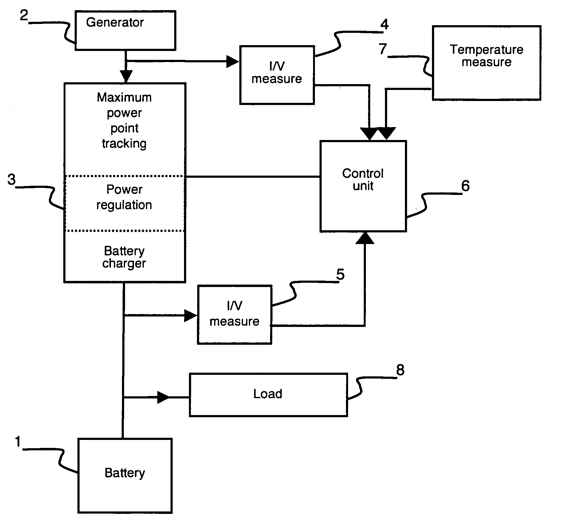
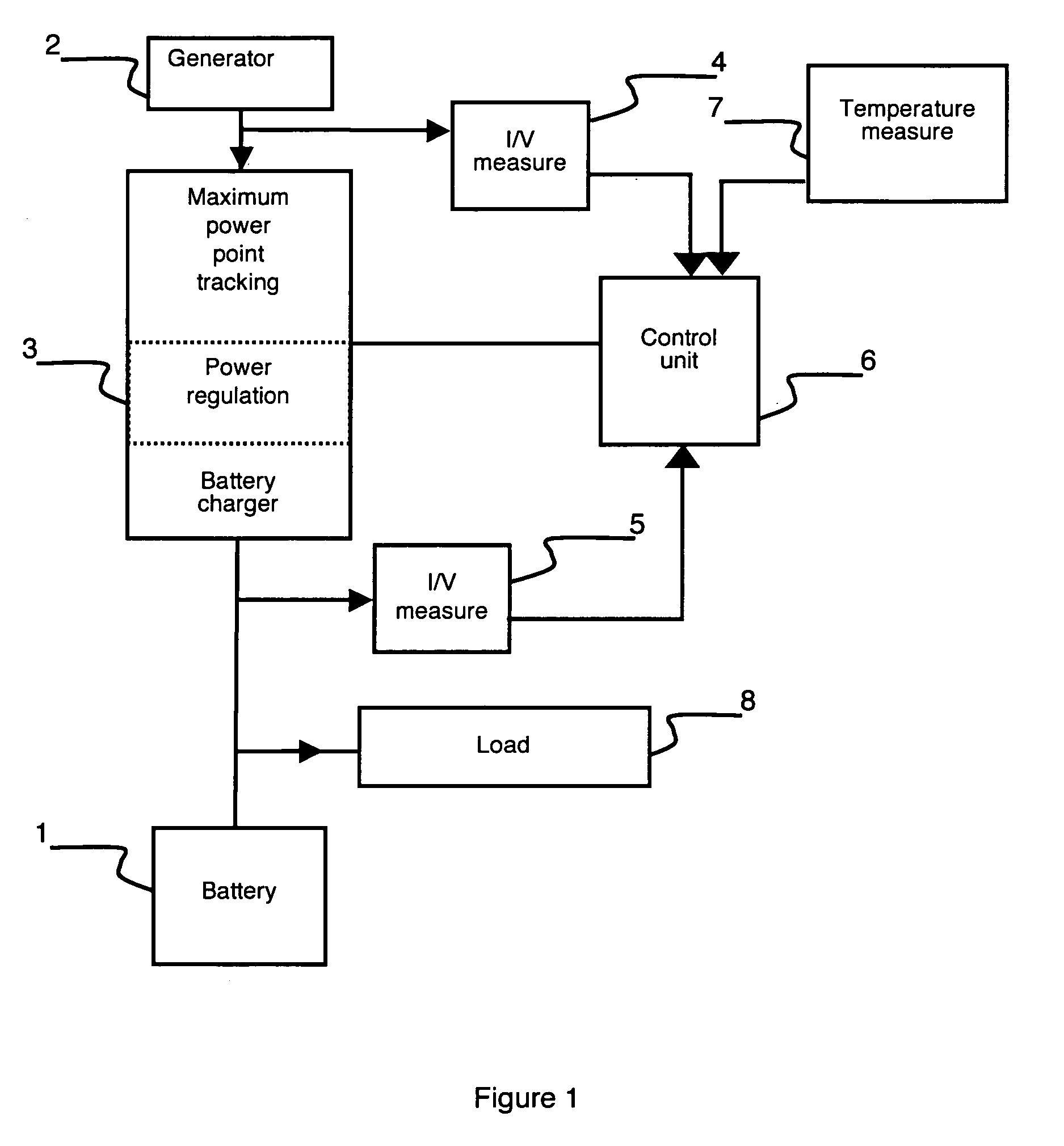
[0022]As illustrated in FIG. 1, the autonomous system comprises at least one battery 1 acting as power storage element, a power generator 2, and a power regulator 3 connected between the generator 2 and the battery 1. Measuring circuits 4 and 5, for respectively measuring the voltage and current at the output of the generator 2 and at the terminals of the battery 1, are connected to a control unit 6, also connected to the power regulator 3. A temperature measurement circuit 7 is also connected to the control unit 6. A load 8 is conventionally supplied with power by the battery 1.

[0023]The temperature measurement circuit 7 preferably comprises at least one ambient temperature measurement sensor and a measurement sensor of the temperature of the battery 1. The control unit 6 can then calculate the temperature difference between the battery 1 and its environment.

[0024]The power generator 2 is for example a photovoltaic panel or a micro-hydraulic or wind power device.

[0025]The power reg...


PUM


Abstract

In an autonomous system, the method for charging a power storage element from a generator comprises temperature measurement, with switching from a first charging mode to a second charging mode in which the voltage is regulated by the temperature. The first charging mode is charging at regulated current to a maximum current value which is a function of the state of charge of the power storage element and of the temperature of the power storage element. Switching is performed when the voltage at the terminals of the power storage element reaches a preset threshold value, itself a function of the value of the current and temperature of the power storage element.

Description

BACKGROUND OF THE INVENTION[0001]The invention relates to a method for charging a power storage element of an autonomous system, from a generator, the method comprising temperature measurement and switching from a first charging mode to a second charging mode when the voltage at the terminals of the power storage element reaches a preset threshold value, the second charging mode being a temperature-regulated voltage charging mode.STATE OF THE ART[0002]Autonomous systems using a renewable power source generally require use of storage of the power produced by intermittence. The most widely used power storage systems are electrochemical accumulators, in particular “lead-acid” batteries. However, new storage technologies, in particular nickel- or lithium-based, are emerging to meet power storage requirements.[0003]In these systems, charging or discharging of a battery is performed under the control of a regulator. The principal role of the regulator is to manage the end of charging and ...

Claims


Application Information

Patent Timeline
IPC IPC(8): H02J7/00
CPCH02J7/0073H02J7/35Y02E70/40H02J7/0071Y02E60/10Y02E60/13
Inventor GENIES, SYLVIELABRUNIE, ANTOINEMATTERA, FLORENCE
Owner COMMISSARIAT A LENERGIE ATOMIQUE ET AUX ENERGIES ALTERNATIVES
Why Eureka
Try Eureka