
System and Apparatus for Dynamically Assigning Functions for Keys of a Computerized Keyboard Based on the Analysis of Keystrokes

a computerized keyboard and function technology, applied in the field of computer input devices, can solve the problems of limited function of data entry keys on the keyboard or keypad, keyboard key sensitivity, and many conventional means for equating functions to keystrokes are so limited, and achieve the effect of improving data entry results efficiency and configurable keystroke sensitivity

Inactive Publication Date: 2008-11-13
LEGACY IP A CALIFORNIA +1
View PDF5 Cites 18 Cited by
  • Summary
  • Abstract
  • Description
  • Claims
  • Application Information

AI Technical Summary

Benefits of technology

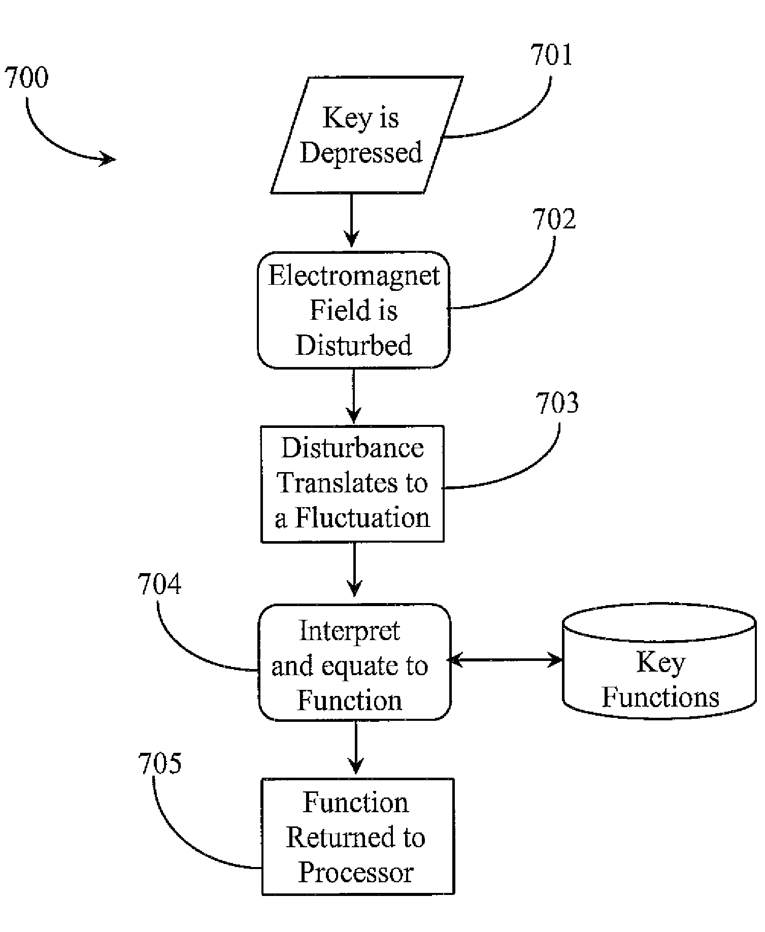
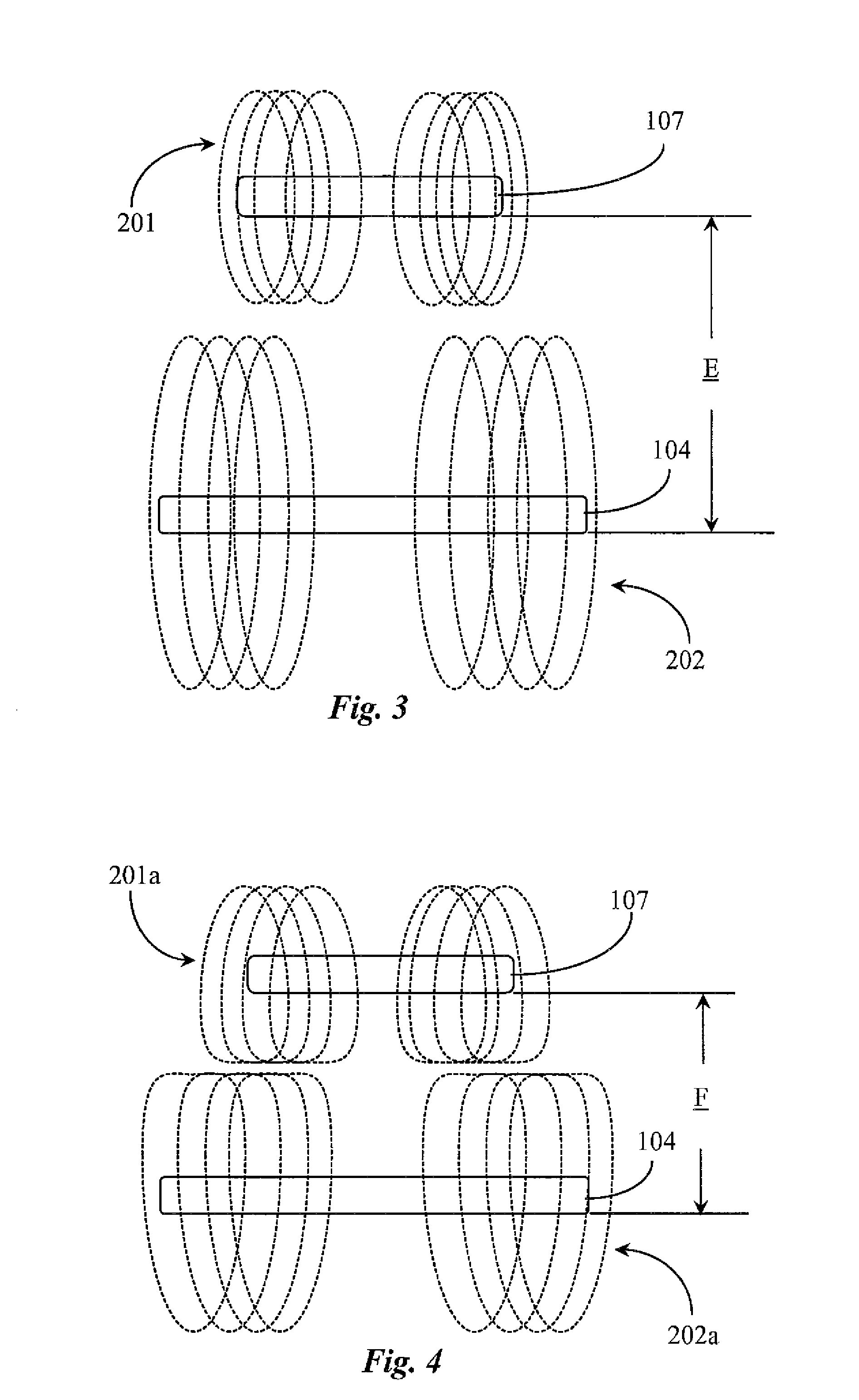
"The patent text describes a new technology for data entry keys on keyboards or keypads. These keys have a unique design that allows for monitoring of key movements and dynamic selection of different functions based on the characteristics of the key movements. This technology provides greater flexibility and efficiency in data entry, as users can adjust the sensitivity of the keys to their needs. The key design includes a permanent magnet and an electromagnet, which work together to produce a magnetic field that is disturbed during a key press, resulting in a measurable change in the current through the electromagnet. This change is analyzed to select the specific function for the key. The technology can be used in existing keyboards and keypads without requiring any extra work by the user."

Problems solved by technology

A problem stated above is that functions for data entry keys on a keyboard or keypad are limited to pre-assigned functions dependent on operative mode and many of the conventional means for equating functions to keystrokes are so limited.
Another problem stated above is that keyboard key sensitivity is a function of the mechanics of the key and cannot be configured by a user.
One by product of having only pre-assigned key functions is a lack of flexibility.
Another byproduct of static sensitivity of the keys is that certain users may not be able to use certain keyboards for typing.

Method used


Image

  • System and Apparatus for Dynamically Assigning Functions for Keys of a Computerized Keyboard Based on the Analysis of Keystrokes
  • System and Apparatus for Dynamically Assigning Functions for Keys of a Computerized Keyboard Based on the Analysis of Keystrokes
  • System and Apparatus for Dynamically Assigning Functions for Keys of a Computerized Keyboard Based on the Analysis of Keystrokes

Examples


Embodiment Construction

[0026]According to an embodiment of the present invention, the inventor provides a magnetically enhanced “smart keysystem for a computer keyboard or device keypad, system capable of analyzing keystroke attributes and assigning functions based on the analysis. The methods and apparatus of the present invention are explained in enabling detail using the provided illustrations.

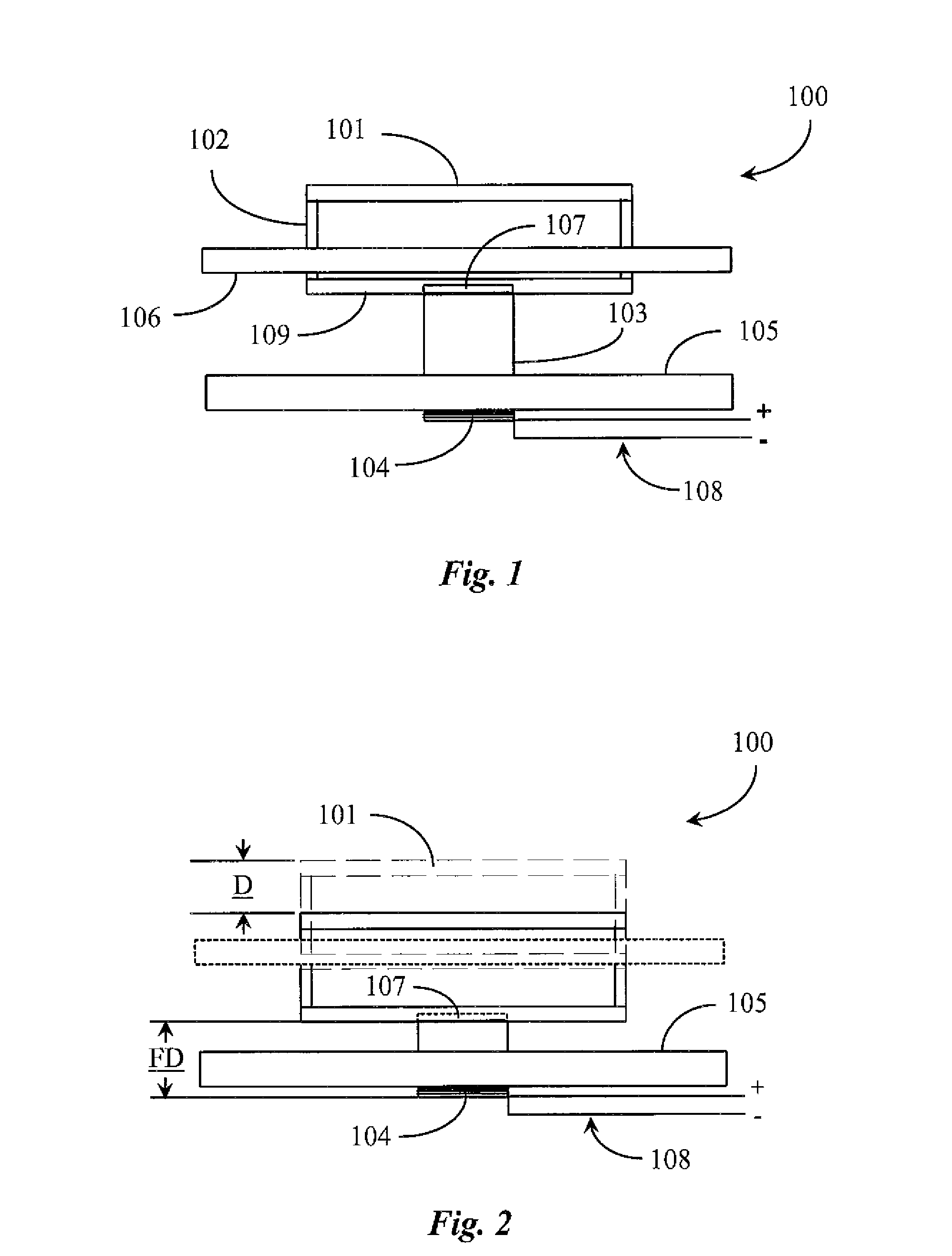
[0027]FIG. 1 is an elevation view of an electromagnetic key 100 in an elevated state according to an embodiment of the present invention. Electromagnetic key 100, also referred to herein as a “smart key”100 is provided and may be incorporated with a plurality of same and / or similar “smart keys” on a computer keyboard or keypad comprising a system of such keys.

[0028]In one embodiment key 100 has a key frame incorporating at least a top key plate 101 and a bottom key plate 109. Plates 101 and 109 are held apart in a substantially parallel configuration to each other and in substantial true position in this exampl...


PUM


Abstract

A computer data entry includes a key frame including at least a top plate and a bottom plate, a key motion mechanism for enabling a range of vertical movement of the key, a permanent magnet producing a magnetic field affixed to the key frame, and an electromagnet affixed to the key motion mechanism. The permanent magnetic field repels the electromagnetic field when current is introduced into the electromagnet such that upon key depression, a disturbance in the electromagnetic field occurs as a result of like polarity of the magnetic fields, the disturbance analyzed to dynamically select a specific input function for the key.

Description

CROSS-REFERENCE TO RELATED APPLICATIONS[0001]The present invention claims priority to a U.S. provisional patent application Ser. No. 60 / 917,464 entitled Magnetically Enhanced Computer Key filed on May 11, 2007 disclosure of which is incorporated in its entirety at least be reference.BACKGROUND OF THE INVENTION[0002]1. Field of the Invention[0003]The present invention is in the field of computer input devices, more particularly, keyboard and keypad input devices and pertains to systems and apparatus for analyzing physical characteristics of keystrokes for the purpose of dynamic assignment of key input function.[0004]2. Discussion of the State of the Art[0005]The computer keyboard has long been the most relied upon input device for computer appliances. Most keyboard input devices are serial input devices comprising a plurality of keys connected individually to circuits on a printed circuit board such that data input to a program running on the computer appliance can be achieved by typ...

Claims


Application Information

Patent Timeline
Patent Type & Authority Applications(United States)
IPC IPC(8): H03M11/00
CPCG06F3/0202H03M11/06
Inventor GARRETT, PETER
Owner LEGACY IP A CALIFORNIA
Learn More