Display apparatus and touch display apparatus

a display apparatus and touch display technology, applied in the field of display apparatus and touch display apparatus, can solve the problems of signal delay and worsening of signal delay problems, and achieve the effects of enhancing display quality and efficiency, reducing the maximum time constant, and enhancing the charging efficiency of data lines

Active Publication Date: 2016-02-18
INNOLUX CORP
View PDF0 Cites 8 Cited by
  • Summary
  • Abstract
  • Description
  • Claims
  • Application Information

AI Technical Summary

Benefits of technology

[0019]As mentioned above, in the display apparatus and touch display apparatus of the invention, the first control line and the second control line are disposed so that a maximum time constant from the driving unit to the switch units can be less than R*C / 4. In comparison with the conventional art, this invention can reduce the maximum time constant so as to enhance the charging efficiency of the data line and further to enhance the display quality and efficiency. Besides, the charging time of the data line is shorter for the high-definition display apparatus and touch display apparatus, so the charging efficiency thereof is more important. Accordingly, this invention can bring more outstanding effectiveness when applied to the high-definition display product or touch apparatus.

Problems solved by technology

However, the delay problem will be generated when the signal of the control line travels for a longer path to reach the farther switch of the multiplexer from the driver IC, i.e. leading to a larger time constant τ, and therefore the signal delay is brought about.
Moreover, with the higher definition, the signal delay problem will become worse.

Method used


Image

  • Display apparatus and touch display apparatus
  • Display apparatus and touch display apparatus
  • Display apparatus and touch display apparatus

Examples


Embodiment Construction

[0025]The present invention will be apparent from the following detailed description, which proceeds with reference to the accompanying drawings, wherein the same references relate to the same elements.

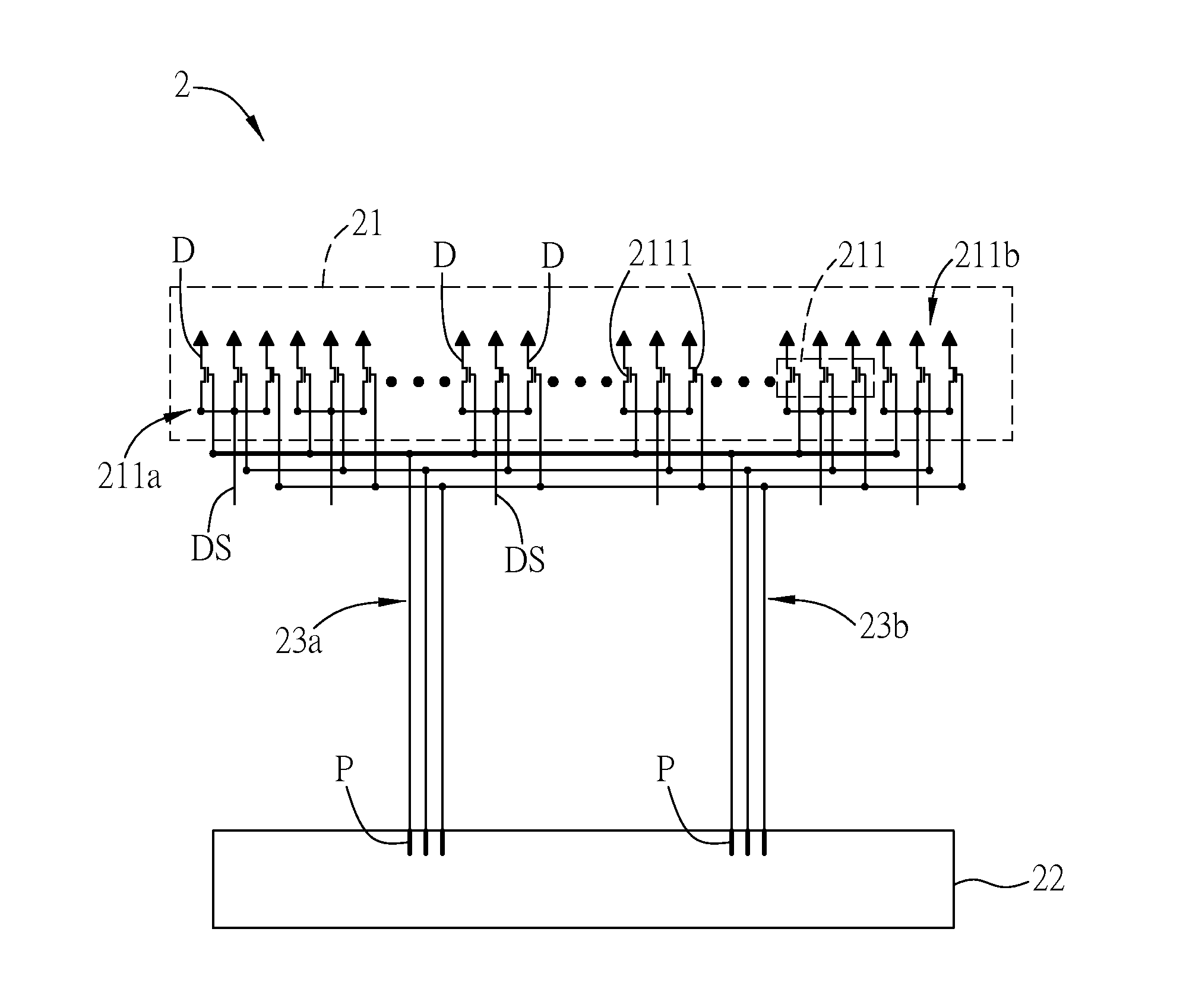
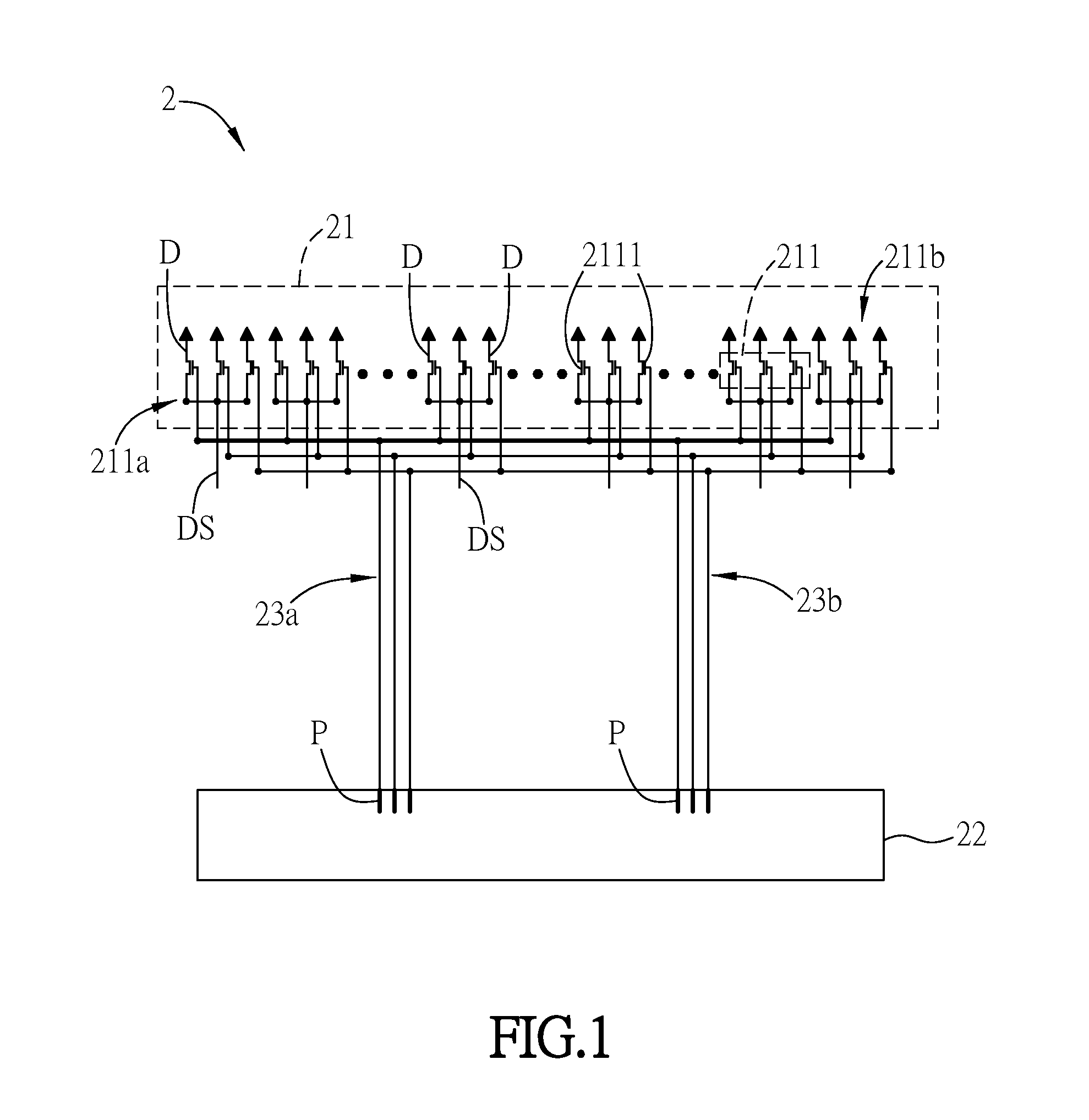
[0026]FIG. 1 is a schematic diagram of a display apparatus 2 of an embodiment of the invention. As shown in FIG. 1, the display apparatus 2 includes a multiplexer circuit 21, a driving unit 22, a first control line 23a and a second control line 23b. The display apparatus 2 is not limited in type, which can be, for example, a non-self-luminous display apparatus such as an LCD apparatus, or a self-luminous display apparatus such as an organic light emitting diode (OLED) display apparatus, or another active matrix display apparatus, or a display apparatus with other functions such as a touch display apparatus. In this embodiment, the display apparatus 2 is an LCD apparatus for example, and the LCD panel is made by the COG (chip on glass) technology. The driving unit 22, the first control...


PUM


Abstract

A display apparatus includes a multiplexer circuit, a driving unit, a first control line and a second control line. The multiplexer circuit includes a plurality of switch units. The first control line is electrically connected with the switch units and the driving unit. The second control line is electrically connected with the switch units and the driving unit. A maximum time constant from the driving unit to the switch units is less than R*C/4, wherein R represents the equivalent resistance of the portion of the first control line between the two switch units which are the farthest from each other, and C represents the equivalent capacitance of the portion of the first control line between the two switch units which are the farthest from each other.

Description

CROSS REFERENCE TO RELATED APPLICATIONS[0001]This Non-provisional application claims priority under 35 U.S.C. §119(a) on Patent Application No(s). 103127976 filed in Taiwan, Republic of China on Aug. 14, 2014, the entire contents of which are hereby incorporated by reference.BACKGROUND OF THE INVENTION[0002]1. Field of Invention[0003]The invention relates to a display apparatus and a touch display apparatus.[0004]2. Related Art[0005]For the active matrix panel, each data line will obtain a shorter charging time with the higher definition. In some panels, a one-to-many multiplexer is generally used for the data line bus and the sequential control signals are also used to control the switches of the multiplexer, and therefore the data lines can be sequentially charged. Accordingly, for an active matrix LCD (liquid crystal display) device with the definition of FHD (1080*1920) and the scan frequency of 60 times per second, the charging time of each data line is about equal to (1 / 60)*(1...

Claims


Application Information

Patent Timeline
Patent Type & Authority Applications(United States)
IPC IPC(8): G09G3/36G06F3/044G09G5/18
CPCG09G3/3688G09G5/18G09G2320/0223G09G2310/0297G06F3/044G06F3/0412G06F3/04164G09G2300/0426
Inventor HEKSTRA, GERBENWATANABE, HIDETOSHILIN, CHENG-HSIAOHSU, MING-CHAOFURUI, YUKO
Owner INNOLUX CORP
Why Eureka
Try Eureka