
Image processing apparatus

a technology of image processing and apparatus, applied in the field of image processing apparatus, can solve the problems of insufficient separation, inability to save contrast, and huge process amount, and achieve the effect of maintaining contras

Inactive Publication Date: 2008-11-13
KK TOSHIBA
View PDF8 Cites 10 Cited by
  • Summary
  • Abstract
  • Description
  • Claims
  • Application Information

AI Technical Summary

Benefits of technology

The present invention provides an image processing apparatus that can compress the dynamic range of an image while maintaining the contrast. This is achieved by dividing the image into multiple domains and calculating the average brightness and illumination component brightness for each domain. The gain of each pixel is then corrected based on the illumination component brightness to achieve the desired effect. This approach reduces the amount of processing required and allows for dynamic range compression without compromising the contrast of the image.

Problems solved by technology

Consequently, the separation cannot be sufficiently executed and the contrast cannot be saved.
The conventional image processing apparatus has a problem that a filter of large kernel size is required to obtain the illumination components of the pixels in a wide range and the process amount becomes enormous.

Method used


Image

  • Image processing apparatus
  • Image processing apparatus
  • Image processing apparatus

Examples


Embodiment Construction

[0024]An embodiment of the present invention will be described with reference to the accompanying drawings.

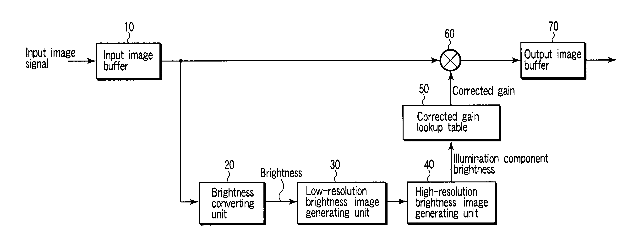
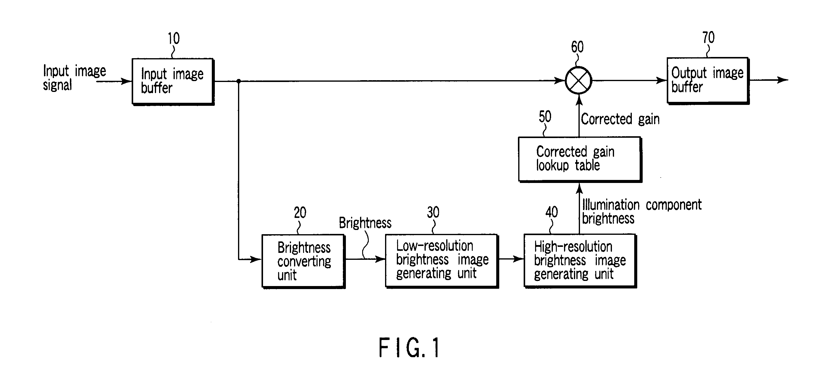
[0025]FIG. 1 shows a configuration of an image processing apparatus, such as a cellular phone and a portable computer, according to the embodiment of the present invention. The image processing apparatus comprises an input image buffer 10, a brightness converting unit 20, a low-resolution brightness image generating unit 30, a high-resolution brightness image generating unit 40, a corrected gain lookup table 50, a correcting unit 60 and an output image buffer 70.

[0026]The input image buffer 10 temporarily buffers the input image signal input in the image processing apparatus to process the input image signal by the units at the subsequent stage. The input image signal temporarily buffered by the input image buffer 10 is output to the brightness converting unit 20 and the corrected gain lookup table 50.

[0027]The brightness converting unit 20 obtains the brightness of each of the...


PUM


Abstract

A brightness converting unit obtains brightness of each of the pixels. The low-resolution brightness image generating unit divides an image based on the input image signal into a plurality of domains, and obtains an average brightness of each of the domains, on the basis of the brightness obtained by the brightness converting unit. A high-resolution brightness image generating unit obtains brightness of each of the pixels included in the image based on the input image signal by weighting the average brightness obtained for each of the domains by a distance from a central portion of the domain. On the basis of the obtained brightness, the corrected gain lookup table determines a corrected gain, and the correcting unit corrects the input image signal.

Description

CROSS-REFERENCE TO RELATED APPLICATIONS[0001]This application is based upon and claims the benefit of priority from prior Japanese Patent Application No. 2007-124765, filed May 9, 2007, the entire contents of which are incorporated herein by reference.BACKGROUND OF THE INVENTION[0002]1. Field of the Invention[0003]The present invention relates to an image processing apparatus configured to correct image data.[0004]2. Description of the Related Art[0005]By using single-scale Retinex algorithm for synthesizing enhanced images in which smoothed brightness components, edges and the like are extracted and enhanced, characteristics such as line segments, edges and the like in the images have been prevented from becoming small due to compression of the dynamic range (cf., for example, Jpn. Pat. Appln. KOKAI Publication No. 2005-182232).[0006]When the image data is corrected in a system of separating the luminance into illumination components and contrast components by backlight correction ...

Claims


Application Information

Patent Timeline
Patent Type & Authority Applications(United States)
IPC IPC(8): H04N5/57
CPCH04N1/4072
Inventor MORIMOTO, MASAMI
Owner KK TOSHIBA
Learn More