
Carbon nanotube glazing technology

a carbon nanotube and glazing technology, applied in the direction of parallel plane units, transportation and packaging, coatings, etc., can solve the problems of low visible reflectance, difficult to identify specific combinations of film thicknesses and compositions, and difficult to provide glazing

Active Publication Date: 2008-11-13
CARDINAL CG
View PDF37 Cites 37 Cited by
  • Summary
  • Abstract
  • Description
  • Claims
  • Application Information

AI Technical Summary

Problems solved by technology

It is challenging to provide a glazing that exhibits a well balanced set of properties.
For example, when a glazing includes a glass sheet bearing a coating, such as a low-emissivity coating, it is challenging to achieve a desired level of visible transmittance, low visible reflectance, good thermal insulating properties, neutral color, and good durability.
In particular, it is difficult to identify specific combinations of film thicknesses and compositions that achieve an exceptional balance of coating properties.
Many adjustments, however, adversely impact other desired coating properties.
It is also challenging to provide coated glass that can be produced in a cost-effective manner.
For example, transparent conductor coatings, such as ITO coatings, can be expensive to produce.
Materials for producing ITO coatings are also limited in supply.
ITO coatings also may have less than desirable durability.
For example, ITO coatings may be relatively prone to scratching.
Desirable properties are even more difficult to achieve when coatings are subjected to heat treatment.
Certain coatings, for example ITO coatings, may not withstand such high temperature processing without some deterioration.
One limitation of conventional laminated glass assemblies resides in the strength of the polymer interlayers.
In some cases, the interlayer may break down over time so that the adhesion between the panes also breaks down.

Method used


Image

  • Carbon nanotube glazing technology
  • Carbon nanotube glazing technology
  • Carbon nanotube glazing technology

Examples


Embodiment Construction

[0032]The following detailed description is to be read with reference to the drawings, in which like elements in different drawings have like reference numbers. The drawings, which are not necessarily to scale, depict selected embodiments and are not intended to limit the scope of the invention. Skilled artisans will recognize that the given examples have many alternatives that fall within the scope of the invention.

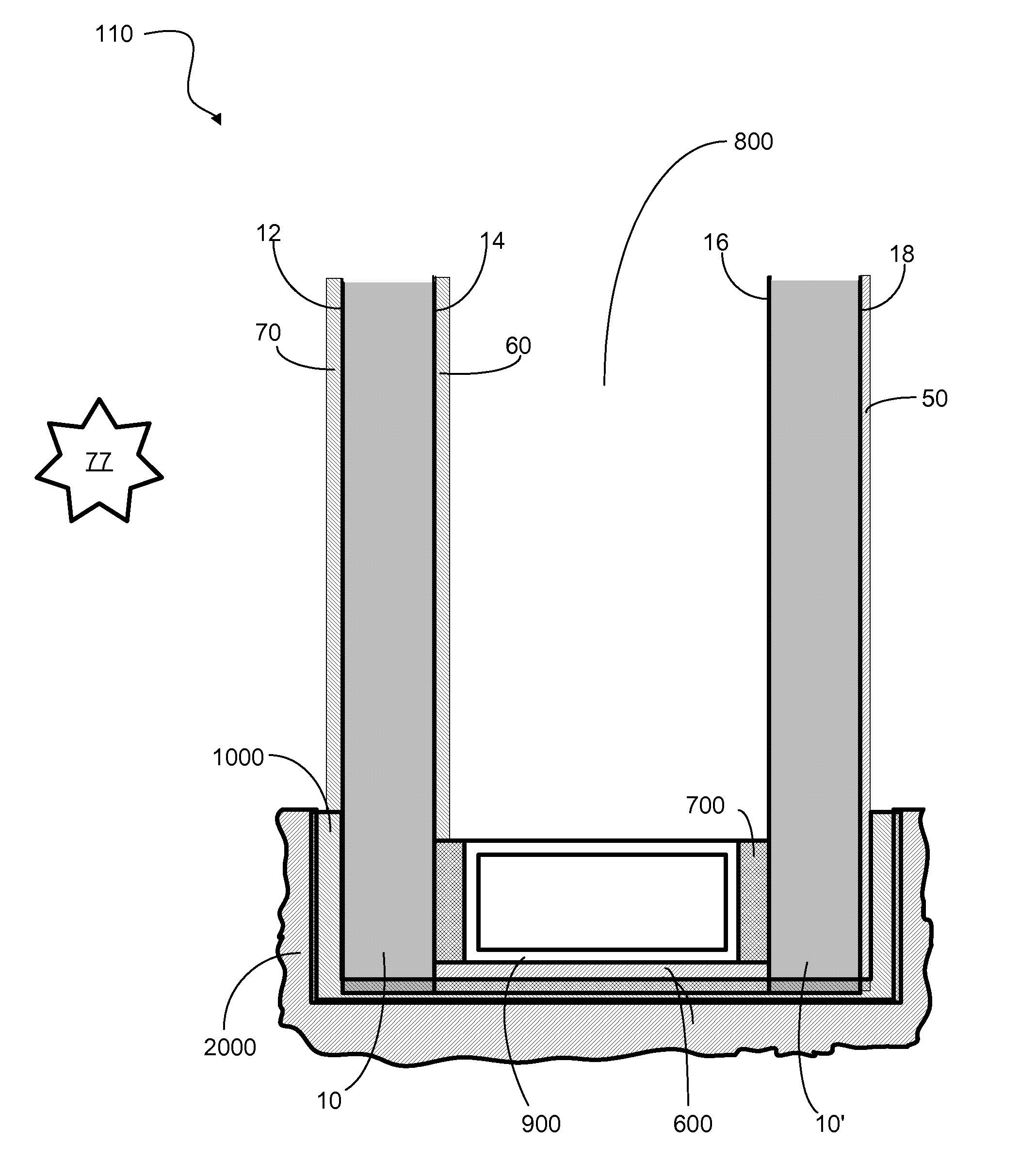
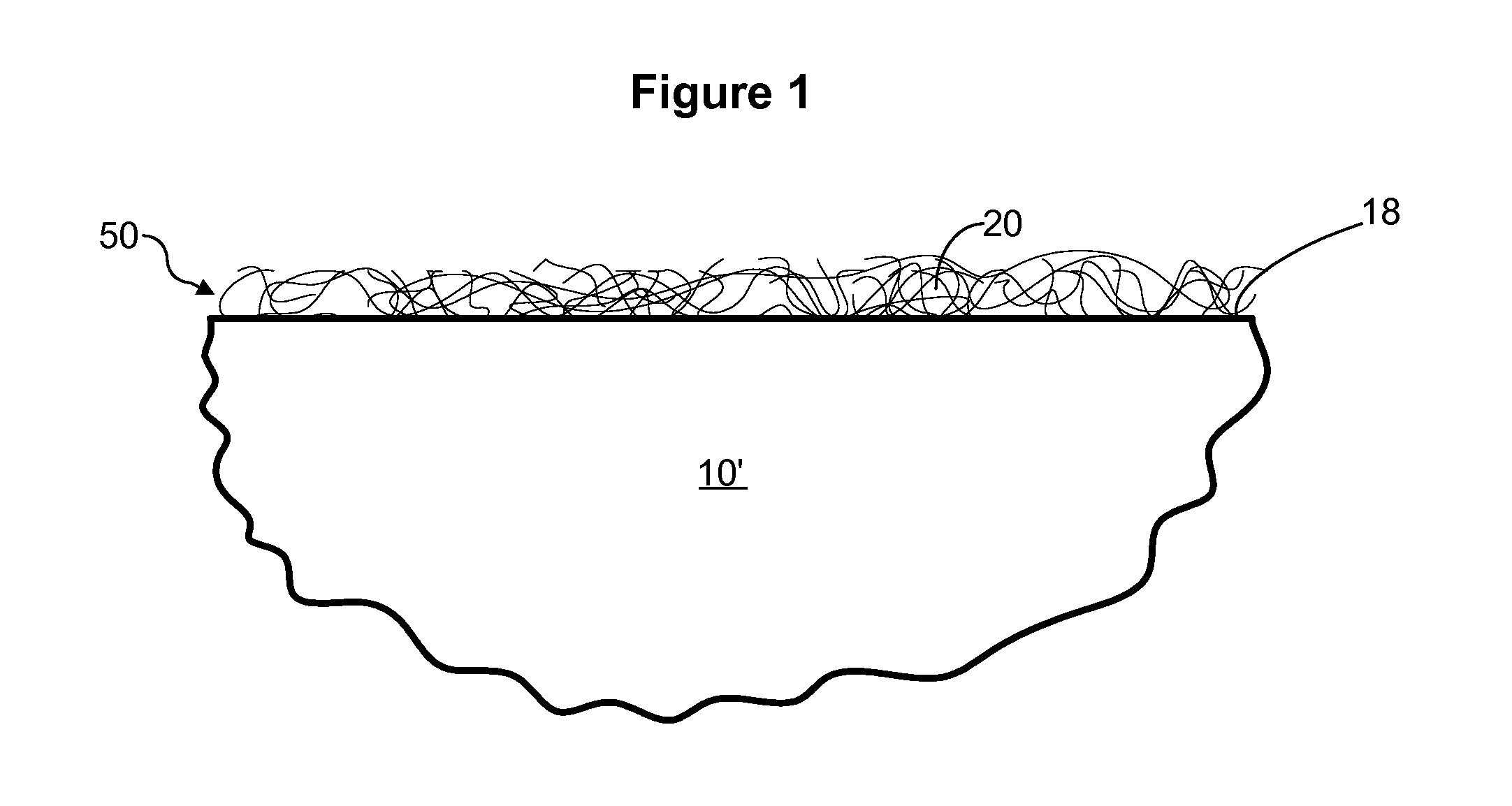
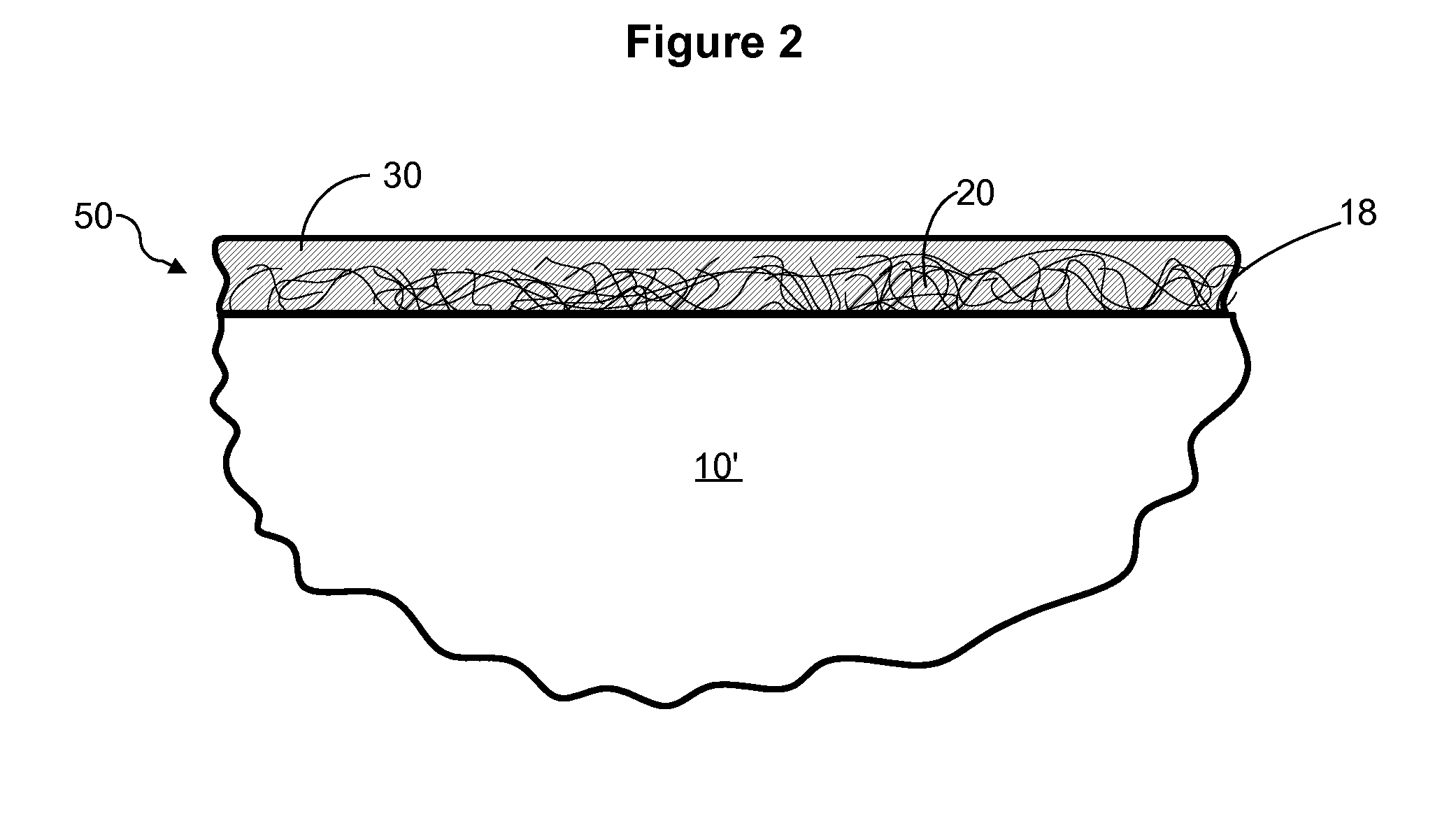
[0033]Many embodiments of the invention involve a coated substrate. A wide variety of substrate types are suitable for use in the invention. In some embodiments, the substrate 10, 10′ is a sheet-like substrate having generally opposed first 12, 16 and second 14, 18 major surfaces. For example, the substrate can be a sheet of transparent material (i.e., a transparent sheet). The substrate, however, is not required to be a sheet, nor is it required to be transparent.

[0034]The substrate can optionally be a component of any of a variety of building materials. Examples of ant...


PUM

PropertyMeasurementUnit
thicknessaaaaaaaaaa
weight ratioaaaaaaaaaa

Abstract

The invention provides a glazing that includes a substrate on which there is provided a coating comprising carbon nanotubes. The glazing can be an IG unit comprising two spaced-apart panes bounding a between-pane space, the IG unit having at least one exterior surface on which there is provided a transparent conductor coating comprising carbon nanotubes. The glazing can alternatively be a laminated glass assembly comprising two panes of glass and an interlayer comprising carbon nanotubes sandwiched therebetween. Monolithic substrate embodiments are also provided. In certain embodiments, the coating comprises both dielectric film and carbon nanotubes.

Description

CROSS-REFERENCE TO RELATED APPLICATION[0001]The present application claims priority to U.S. Application No. 60 / 817,997, filed Jun. 30, 2006, the entire disclosure of which is incorporated herein by reference.FIELD OF THE INVENTION[0002]The present invention provides coatings for substrates, such as glass and the like. More particularly, the invention provides coatings including carbon nanotubes. The invention also provides methods of depositing such coatings onto glass sheets and other substrates.BACKGROUND OF THE INVENTION[0003]Glass sheets and other substrates can be coated with a stack of transparent, metal-containing films to vary the optical properties of the coated substrates. Particularly desirable are coatings characterized by their ability to readily transmit visible light while minimizing the transmittance of other wavelengths of radiation, especially radiation in the infrared spectrum. Known coatings that reflect infrared radiation include low-emissivity coatings and also...

Claims


Application Information

Patent Timeline
Patent Type & Authority Applications(United States)
IPC IPC(8): E06B3/00
CPCB32B17/06B32B17/10036B32B17/10743B32B17/10761C03C17/007Y10T428/30C03C2217/42C03C2217/45C03C2217/475C03C2217/91E06B3/67C03C17/22
Inventor KRISKO, ANNETTE J.BURROWS, KEITH J.
Owner CARDINAL CG
Learn More