Blood pump system and method of operation

a blood pump and pump technology, applied in the field of blood pump systems, can solve the problems of reducing the pumping capability of the native heart and vad, the unsatisfactory performance of the closed loop control system, and the inability to adjust the pump speed in response to a monitored physiologic parameter

Inactive Publication Date: 2008-11-13
RELIANTHEART
View PDF20 Cites 56 Cited by
  • Summary
  • Abstract
  • Description
  • Claims
  • Application Information

AI Technical Summary

Problems solved by technology

First a blood pump may completely replace a human heart that is not functioning properly, or second, a blood pump may boost blood circulation in patients whose heart is still functioning although pumping at an inadequate rate.
However, prior art closed loop control systems—varying the pump speed in response to a monitored physiologic parameter—have largely been unsatisfactory.
“Excess Suction” occurs when the pressure in the inflow cannula decreases significantly—the pump begins to “suck” the ventricle closed, which would greatly reduce the pumping capability of the native heart and VAD.

Method used


Image

  • Blood pump system and method of operation
  • Blood pump system and method of operation
  • Blood pump system and method of operation

Examples


Embodiment Construction

[0030]Illustrative embodiments of the invention are described below. In the interest of clarity, not all features of an actual implementation are described in this specification. It will of course be appreciated that in the development of any such actual embodiment, numerous implementation-specific decisions must be made to achieve the developers' specific goals, such as compliance with system-related and business-related constraints, which will vary from one implementation to another. Moreover, it will be appreciated that such a development effort might be complex and time-consuming, but would nevertheless be a routine undertaking for those of ordinary skill in the art having the benefit of this disclosure.

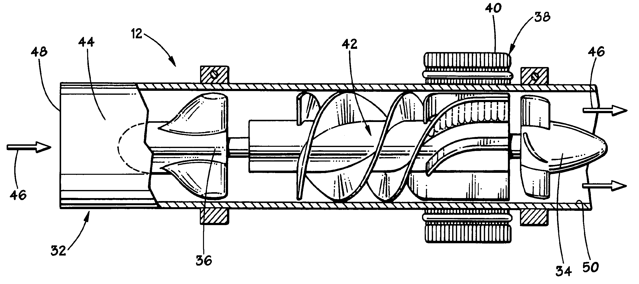
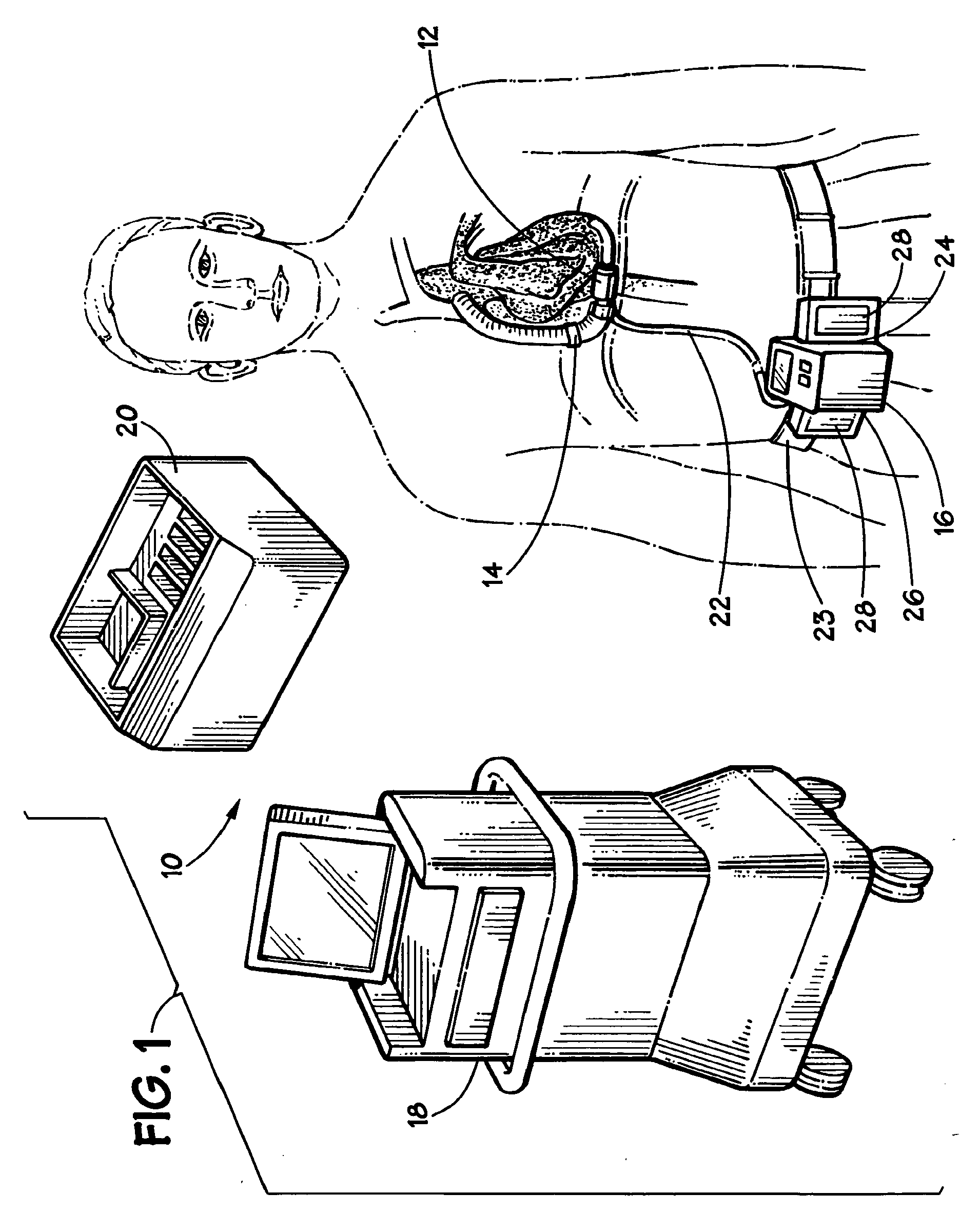
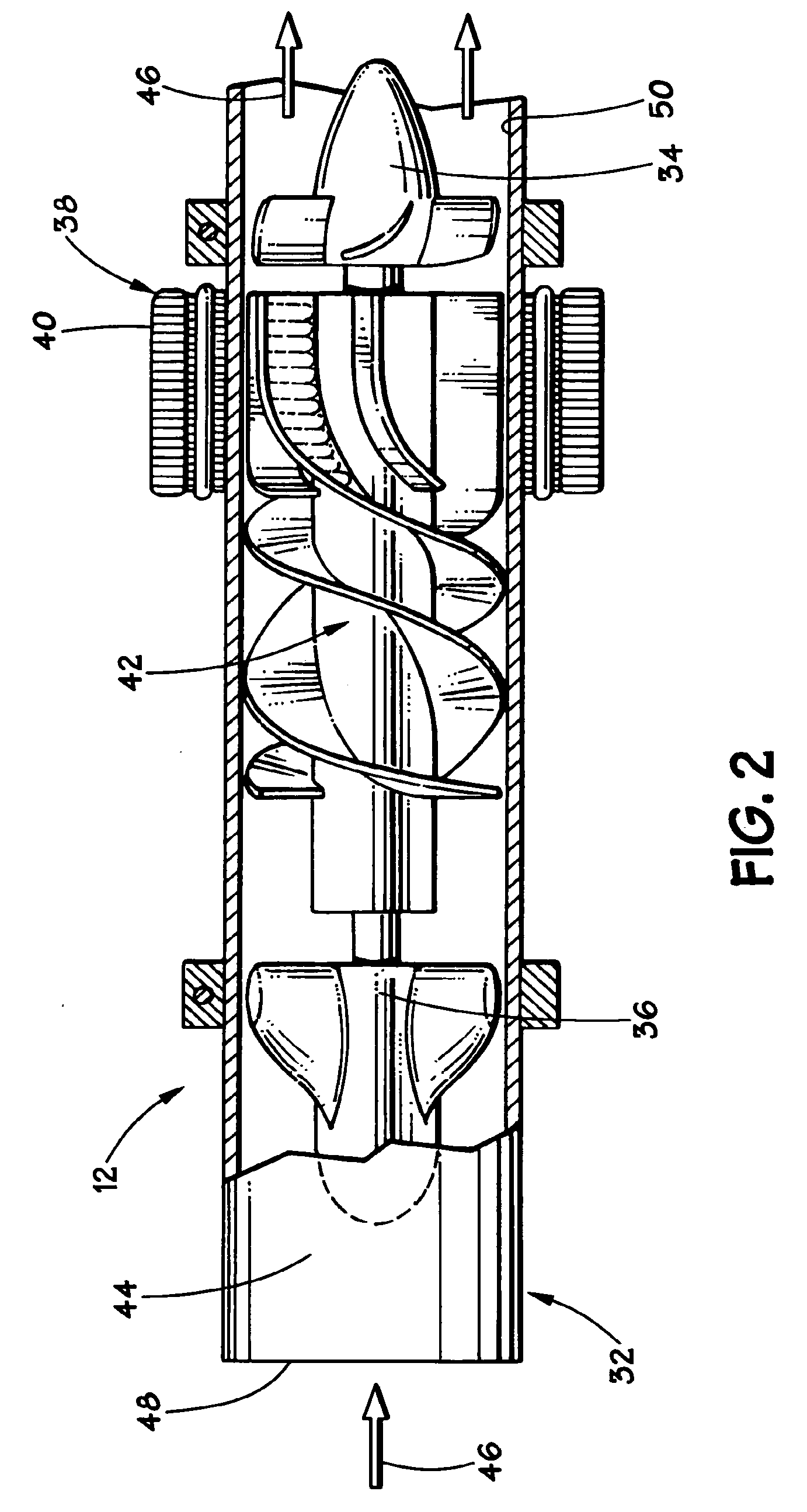
[0031]Turning to the figures, FIG. 1 illustrates a ventricle assist device (VAD) system 10 such as disclosed in U.S. Pat. No. 6,183,412, which is commonly assigned and incorporated herein by reference in its entirety. The VAD system 10 includes components designed for implantatio...


PUM


Abstract

A blood pump system includes a blood pump having a motor with a rotor and a stator. The stator has a plurality of stator windings situated therein. A motor controller is coupled to the motor, and a processor has inputs coupled to the motor controller for receiving a time continuous signal from the pump. The processor is programmed to transform the time continuous signal to the frequency domain, and control the pump and detect excess suction in response to the time continuous signal in the frequency domain.

Description

CROSS-REFERENCE TO RELATED APPLICATIONS[0001]This application is a continuation of U.S. application Ser. No. 10 / 675,669, (Sep. 30, 2003), now U.S. Pat. No. 7,396,327, issued Jul. 8, 2008. U.S. application Ser. No. 10 / 675,669 is a continuation-in-part of International Application No. PCT / US03 / 20268 (Jun. 26, 2003), which is a non-provisional of U.S. Provisional Application No. 60 / 319,358 (Jun. 26, 2002); International Application No. PCT / US03 / 18859 (Jun. 13, 2003), which is a non-provisional of U.S. Provisional Application No. 60 / 319,318 (Jun. 14, 2002); International Application No. PCT / US03 / 00516 (Jan. 8, 2003), which is a non-provisional of U.S. Provisional Application No. 60 / 346,555 (Jan. 8, 2002); and International Application No. PCT / US03 / 00273 (Jan. 7, 2003), which is a non-provisional of U.S. Provisional Application No. 60 / 346,721 (Jan. 7, 2002). Each of the applications referenced above is incorporated herein by specific reference.BACKGROUND[0002]1. Field of the Disclosure[0...

Claims


Application Information

Patent Timeline
Patent Type & Authority Applications(United States)
IPC IPC(8): A61N1/362A61M60/178A61M60/237A61M60/422A61M60/515A61M60/538A61M60/546A61M60/569
CPCA61M1/101A61M1/1086A61M2205/3334A61M2230/06Y10S415/90A61M1/122A61M1/125A61M60/422A61M60/148A61M60/546A61M60/237A61M60/178A61M60/538A61M60/569A61M60/515
Inventor MORELLO, GINO F.
Owner RELIANTHEART
Why Eureka
Try Eureka