Control apparatus for a source of rotational drive force

a control apparatus and rotational drive technology, applied in the direction of machine/engine control, process and machine control, force/torque/work measurement apparatus, etc., can solve the problems of reducing the precision of various controls, requiring a comparatively long dead time, and high precision, so as to prevent hunting and reduce or prevent deviation

Inactive Publication Date: 2008-11-13
TOYOTA JIDOSHA KK
View PDF8 Cites 8 Cited by
  • Summary
  • Abstract
  • Description
  • Claims
  • Application Information

AI Technical Summary

Benefits of technology

[0006]An object of the present invention is to prevent hunting during control in a control apparatus for a source of a rotational drive force, and to reduce or prevent deviation between actual rotational speed and target rotational speed.

Problems solved by technology

However, even if actual torque approaches or coincides with target torque in accordance with this control, a comparatively long dead time is required until the engine speed actually reaches a level corresponding to the target torque.
However, such a model represents a standard or average relation and does not necessarily match an actual individual internal combustion engine or output transmission system with high precision.
Accordingly, deviation may occur between the engine speed actually reached and the target rotational speed at steady state, which can reduce the precision of various controls.

Method used


Image

  • Control apparatus for a source of rotational drive force
  • Control apparatus for a source of rotational drive force
  • Control apparatus for a source of rotational drive force

Examples


first embodiment

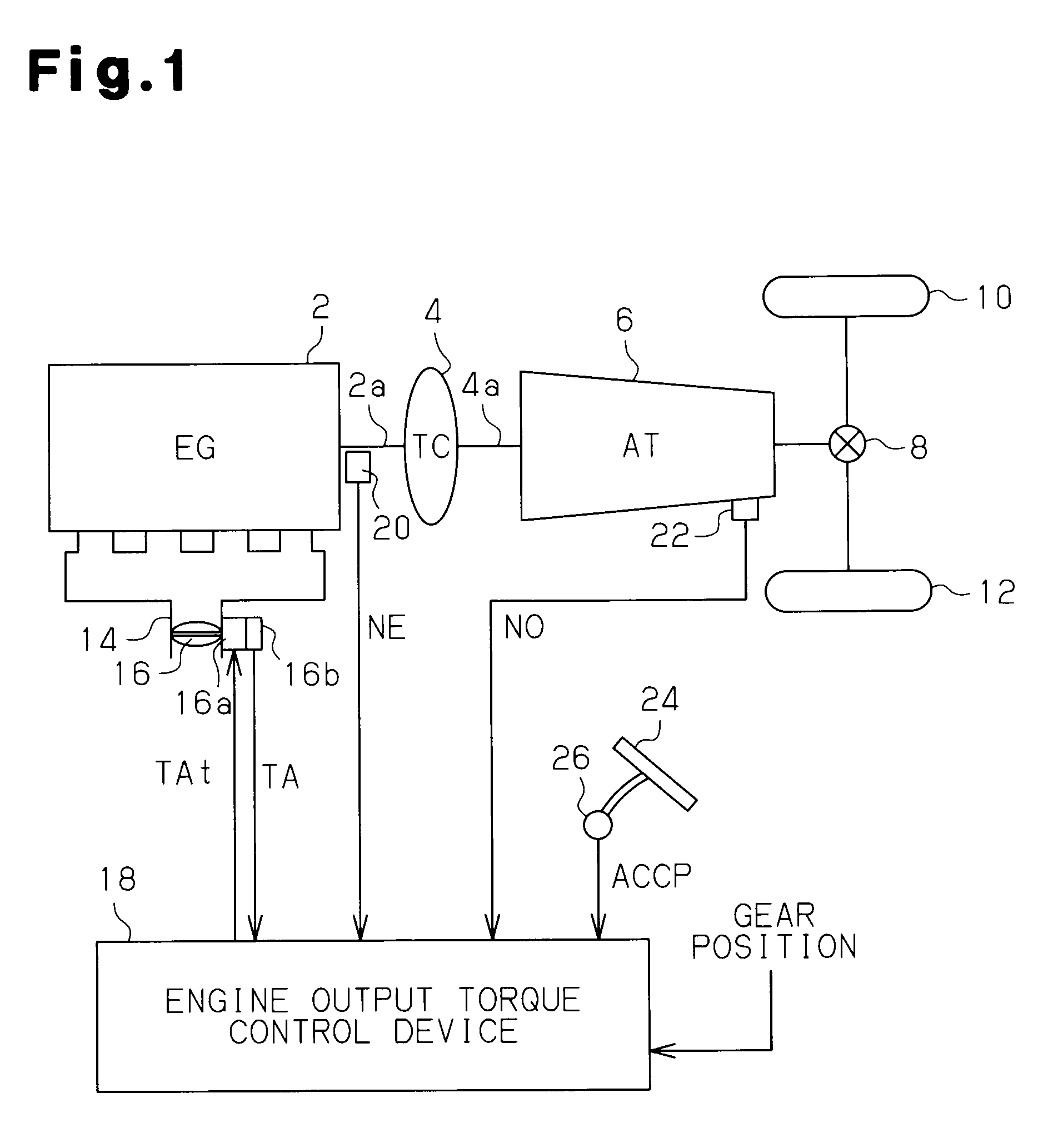
[0021]FIG. 1 shows a block diagram of a source of rotational drive force, a control apparatus for the source of the rotational drive force, and an output transmission system for rotational drive force from the source in accordance with the present invention. In this drive system, rotational drive force output from a gasoline engine 2, which serves as a source of rotational drive force for a vehicle, is transmitted to drive wheels 10 and 12 via a torque converter 4, an automatic transmission 6 and a differential gear 8.

[0022]A throttle valve 16 is provided in an air intake path 14 of the gasoline engine 2. A throttle opening degree TA of the throttle valve 16 can be adjusted by a drive motor 16a. The throttle opening degree TA is detected by a throttle opening degree sensor 16b and is sent to an engine output torque control device 18, which serves as the control apparatus for the source of rotational drive force.

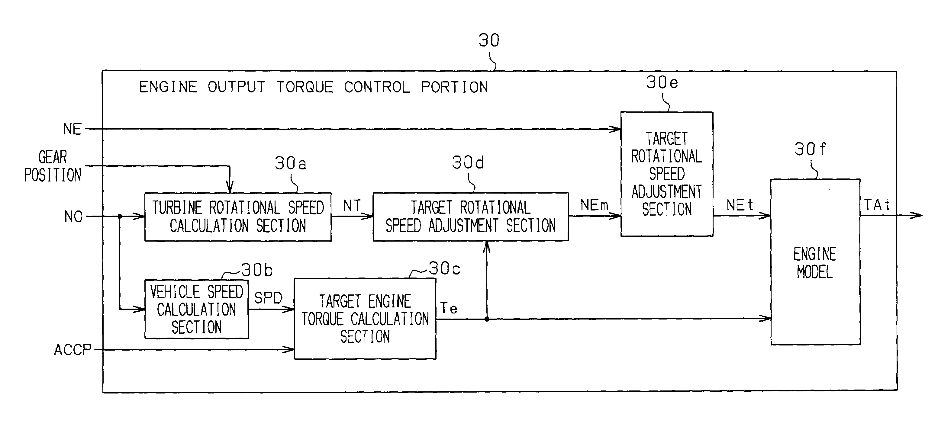
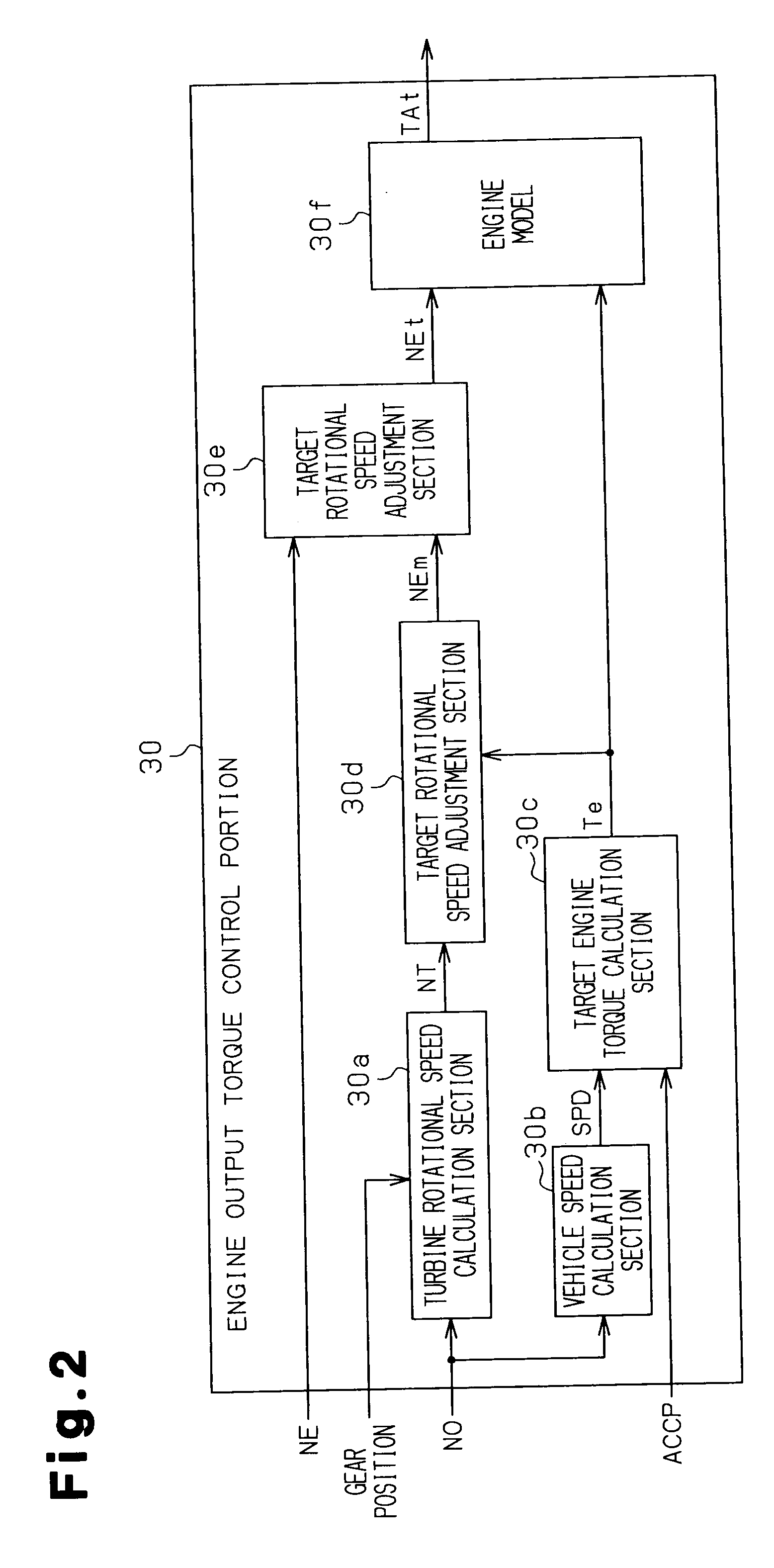
[0023]The engine output torque control device 18 receives a signal from ...

second embodiment

[0053]FIG. 11 is a timing chart showing an example of a control in the When the driver depresses the accelerator pedal 24 (T=t10), the target engine torque Te is rapidly increased (S106). Accordingly, the target model rotational speed NEm is also rapidly increased (S108). The actual rotational speed NE is increased in a delayed manner due to the long dead time. The value of the target model rotational speed NEm corrected by the final correction amount dz calculated by the first order lag process (S222) is set to the target rotational speed NEt in such a manner that the target model rotational speed NEm gradually approaches the actual rotational speed NE (FIG. 10, t≧t10). Therefore, the target rotational speed NEt finally comes close to the actual rotational speed NE, and coincides with the actual rotational speed NE (t≧t11).

[0054]When the driver returns the accelerator pedal 24 (t=t12), the target engine torque Te is rapidly decreased (S106). The target model rotational speed NEm i...

third embodiment

[0069]In the third embodiment, the step S110 (FIG. 12) corresponds to the process of the target rotational speed adjustment section.

[0070]The third embodiment has a following advantage.

[0071](1) Instead of the PI control calculation, the target rotational speed NEt is gradually changed by increments of the fixed rotational speed from the target model rotational speed NEm to the actual rotational speed NE. In accordance with this structure, the same effect as that of the first embodiment may be caused. That is, hunting of the engine during control is prevented and the deviation between the actual rotational speed NE and the target rotational speed Net is reduced or prevented.

[0072]The above embodiments may be modified as follows.

[0073]In the first embodiment mentioned above, the control correction amount dy is continuously determined in accordance with the PI control calculation during the activation of the engine output torque control device 18. However, alternatively, the PI contro...


PUM


Abstract

A control apparatus for controlling a source of rotational drive force based on a target rotational speed. The control apparatus includes a target model rotational speed calculation section, an actual rotational speed detection section, and a target rotational speed adjustment section. The target model rotational speed calculation section calculates a rotational speed corresponding to a target drive force of the source as a target model rotational speed. The actual rotational speed detection section detects an actual of the source. The target rotational speed adjustment section sets the target rotational speed by correcting a value of the target model rotational speed calculated by the target model rotational speed calculation section to gradually approach the actual rotational speed detected by the actual rotational speed detection section. Accordingly, hunting of the engine during control is prevented and the deviation between the actual rotational speed and the target rotational speed is reduced or prevented.

Description

CROSS-REFERENCE TO RELATED APPLICATIONS[0001]The entire disclosure of Japanese Patent Application No. 2007-126452, filed on May 11, 2007, is expressly incorporated by reference herein.FIELD OF THE INVENTION[0002]The present invention relates to a control apparatus for controlling the source of a rotational drive force based on target rotational speed.BACKGROUND[0003]In the field of internal combustion engines for vehicles, for example, there has been proposed an apparatus for controlling an internal combustion engine in such a manner as to achieve a torque output and a vehicle acceleration corresponding to an accelerator operation of the driver as described in Japanese Unexamined Patent Publication Nos. 2003-120349 and 2003-170759.[0004]In the patent documents cited above, in order to calculate a control amount for achieving a target drive force such as a target torque, actual engine speed is used as one of parameters. However, even if actual torque approaches or coincides with targ...

Claims


Application Information

Patent Timeline
Patent Type & Authority Applications(United States)
IPC IPC(8): G05B13/04G05B11/40G05B11/42
CPCB60W20/00F02D31/002F02D41/0225F02D41/1401F02D2250/18F02D2400/12B60W2710/0644B60W2510/0638B60W2520/28B60W10/04B60W2710/1038
Inventor KUWAHARA, SEIJIKAIGAWA, MASATO
Owner TOYOTA JIDOSHA KK
Why Eureka
Try Eureka