Structural Insulated Header

a structural insulation and header technology, applied in the direction of girders, heat-insulating coatings, building repairs, etc., can solve the problems of affecting the stability of the structure, and affecting the integrity of the larger structure, so as to strengthen the load-bearing capacity of the beam

Inactive Publication Date: 2008-11-20
BUCKHOLT RICKY G
View PDF26 Cites 31 Cited by
  • Summary
  • Abstract
  • Description
  • Claims
  • Application Information

AI Technical Summary

Benefits of technology

[0008]The current invention, comprises an enclosed structure to provide a pre-formed modularized insulated beam for forming lintel or header structures. This apparatus and methodology, when combined with a structural metal beam such as an “I” beam, complements and even strengthens the load bearing capacity of the beam. Those skilled in the art can appreciate that an “I” beam can comprise an S beam (standard beam) and a W beam (wide flanged beam). The apparatus can further provide a suitable attachment surface during subsequent construction operations such as nailing, screwing, gluing and the like. In addition to provide adequate insulation value for the metal beam, which is normally a poor thermal insulator, which is extremely important in colder climates.

Problems solved by technology

When a window or door is desired in the structure, that spacing is disrupted and the stresses can become concentrated to the point where the integrity of the larger structure is compromised.
Many times this is support structure is realized by resting the joists or trusses on the beam creating a separate level of structure, which can be unsightly as seen from the floor below.
This solution typically does not have good insulation value and the beam and plywood members can twist and warp and deflect due to load.
This provides a nailing surface for hanging sheetrock, or other facing, and some structural support but has been plagued by structural fatigue due to delamination over time, and the structural limits of wood's load bearing capacity.
Recently, steel “I” beams have been used, which are superior to wood for load bearing capability, but one problem being no sufficient structure for nailing or otherwise attaching other items to the beam.
Due to the incompatibility of steel beams for attaching, the structure to be supported is rested on top of the beam, which creates architectural challenges as mentioned above.
Another issue being the very poor insulation quality of steel without other means for mitigation.

Method used


Image

  • Structural Insulated Header
  • Structural Insulated Header
  • Structural Insulated Header

Examples


Embodiment Construction

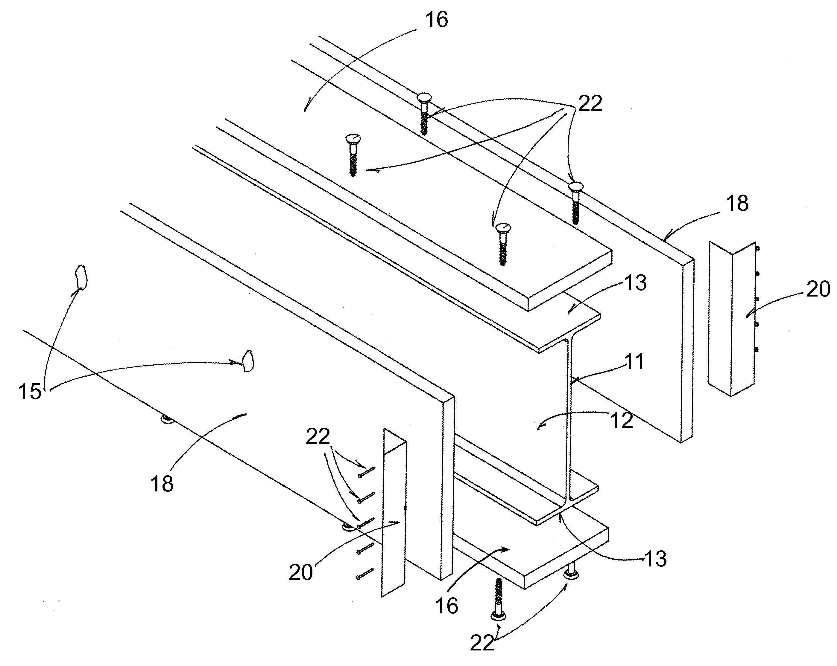
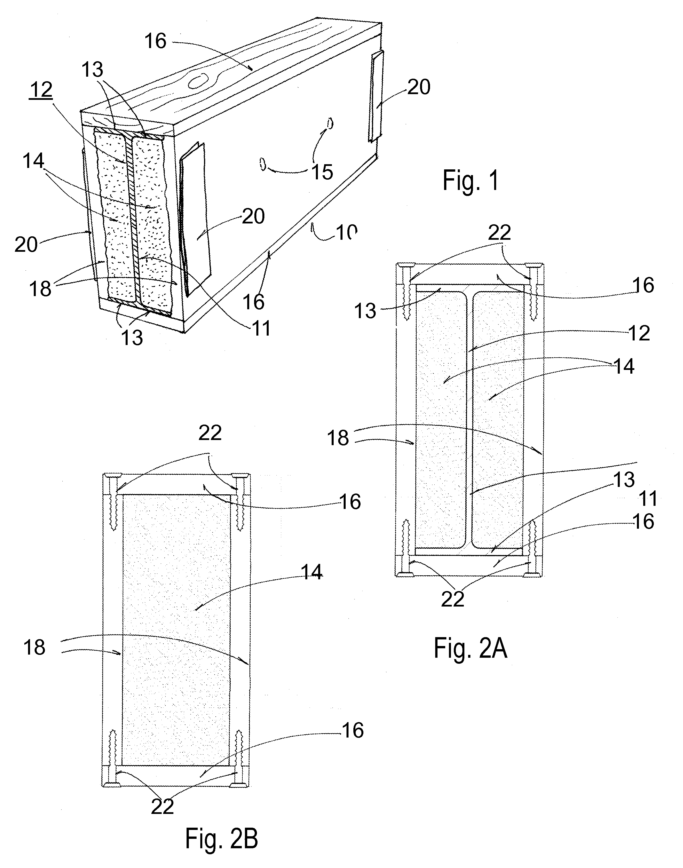
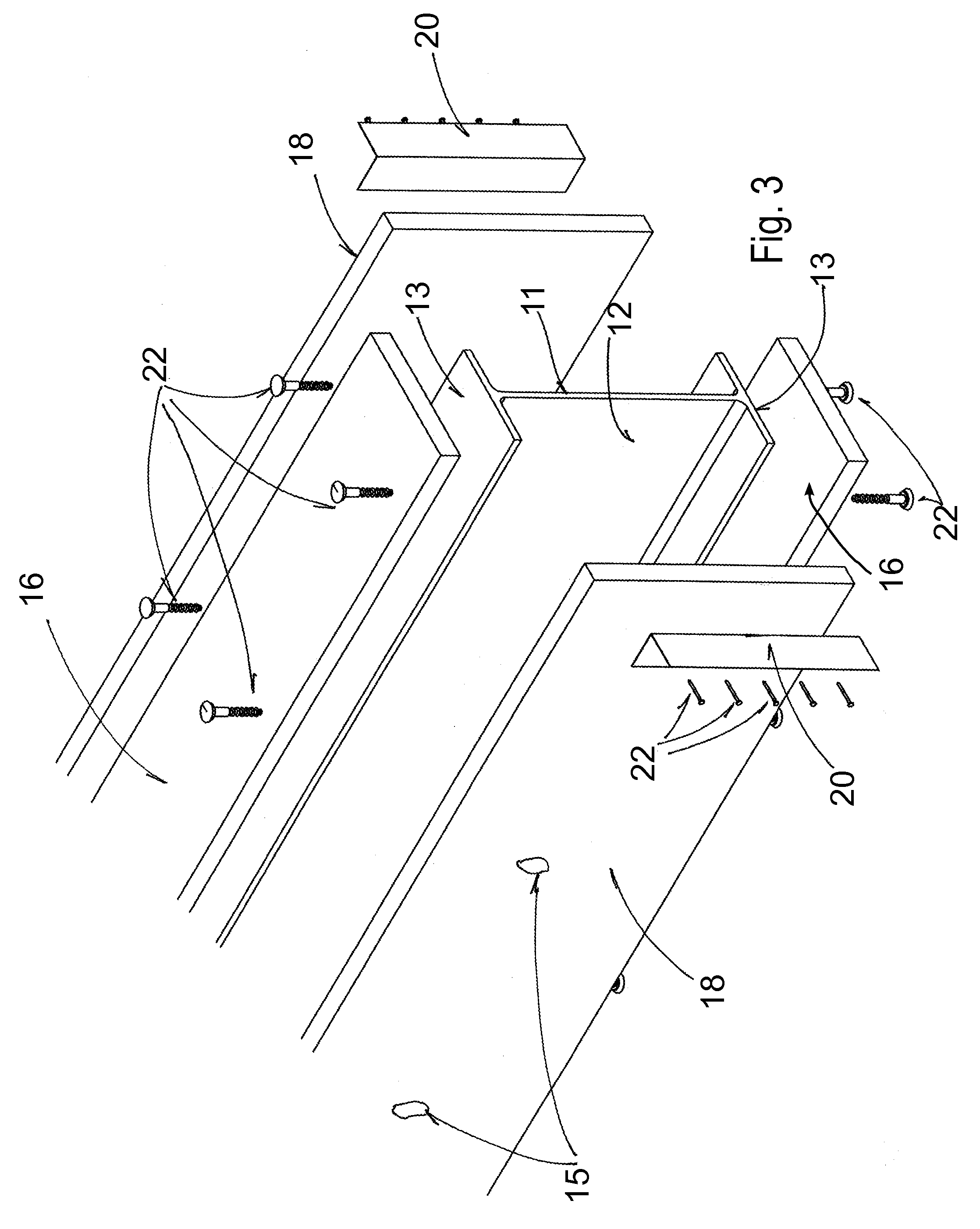
[0047]The structural header as shown in FIGS. 1, 2A, 2B, and 3; consisting primarily of a beam 10, one embodiment of which FIG. 2A is an example, comprising a pre-manufactured box beam 10a comprising a pair of horizontal members 16 connected with a pair of vertical members 18 with an insulation space 14 generally comprised of structural foam.

[0048]In another embodiment shown in FIG. 2B an element known in the trade as an “I” beam is added to the system. The beam 12, which is typically made of a metal such as steel, and is comprised of a web portion 11 which is a vertical member for load bearing, being nominally 8 to 12 inched in height, and two flange portions 13 located on the top and bottom of the web portion 11, being nominally 4 inches in width, for lateral stability. While the beam 12 is typically quite strong compared with wooden framing for construction purposes, it does not provide good nailing or attaching surfaces typically required in conjunction with wooden framing. Addi...


PUM


Abstract

The present invention relates to the construction arts, in particular a new implementation for a structural support member or header for bearing the load of large spans of a floor, wall section above a window, door or garage door. The support member has an insulation which, when used with a steel beam, serves to increase the insulation value. Further the header is modular and can be easily implemented into a variety of architectural structures.

Description

RELATED APPLICATIONS[0001]The present application is a continuation-in-part application of U.S. provisional patent application Ser. No. 60 / 938,512; filed 17 May 2007, included by reference herein and for which benefit of the priority date is hereby claimed.FIELD OF THE INVENTION[0002]The present invention relates to static structures used in the construction arts. In particular a header partition support for use with joists, trusses, windows and doors which is; modularized, insulated and allows ease of construction and attachment surfaces.BACKGROUND OF THE INVENTION[0003]In construction, it is important to bear high structural loads in order to support a building or other similar structure. Typically this has been done by providing a structure framed with 2×4 inch or 2×6 inch etc. cross-sectional studs provided with a regular spacing to support the weight. When a window or door is desired in the structure, that spacing is disrupted and the stresses can become concentrated to the poi...

Claims


Application Information

Patent Timeline
Patent Type & Authority Applications(United States)
IPC IPC(8): E04C3/28E04C3/29E04B1/30E04C1/40
CPCE04B1/78E04B1/944E04C3/127E04C3/29E04C2003/023E04C2003/0452
Inventor BUCKHOLT, RICKY G.
Owner BUCKHOLT RICKY G
Why Eureka
Try Eureka