Unlock instant, AI-driven research and patent intelligence for your innovation.

MEMS emissions sensor system for a turbine engine

Inactive Publication Date: 2008-11-20
SIEMENS ENERGY INC
View PDF5 Cites 8 Cited by
  • Summary
  • Abstract
  • Description
  • Claims
  • Application Information

AI Technical Summary

Benefits of technology

[0011]The method can further include the step of statistically analyzing the measured emissions values. In one embodiment, this step can include performing an average, root mean square, Student's T and/or Monte Carlo statistical analysis. Further, the measured emis

Problems solved by technology

The combustion of fossil fuels in a gas turbine engine, such as in the context of a power generation plant, produces emissions that give rise to environmental concerns.
Current emissions sensor systems that are in compliance with Environmental Protection Agency (EPA) protocol are large, bulky and expensive.
Moreover, experience has revealed that the EPA protocol systems are repeatedly in need of repair.
Such frequent calibration and repair of EPA protocol sensor systems appreciably adds to the cost of power plant operation.

Method used


Image

  • MEMS emissions sensor system for a turbine engine
  • MEMS emissions sensor system for a turbine engine
  • MEMS emissions sensor system for a turbine engine

Examples


Embodiment Construction

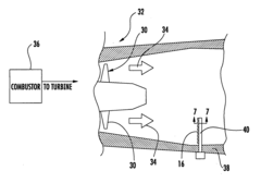
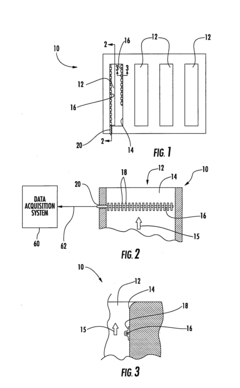
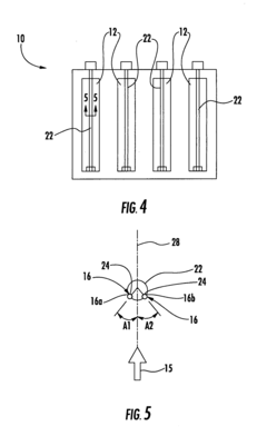
[0021]Embodiments of the invention are directed to a system for measuring various parameters associated with emissions produced during operation of a turbine engine. Aspects of the invention will be explained in connection with various possible systems, but the detailed description is intended only as exemplary. Embodiments of the invention are shown in FIGS. 1-9, but the present invention is not limited to the illustrated structure or application.

[0022]Microelectromechanical systems (MEMS) are a rapidly developing technology. MEMS are devices and machines that can be fabricated using techniques generally used in microelectronics, often to integrate mechanical functions with electrical functions. MEMS devices can be custom designed for a purpose which requires a mechanical action to be controlled by a computer.

[0023]Aspects of the invention are directed to the use of at least one MEMS-based emissions sensor at one or more locations in a turbine engine to measure one or more emission...


PUM


Abstract

Aspects of the invention are directed to the use of microelectromechanical systems (MEMS) based emissions sensors in a turbine engine system to measure one or more emissions values associated with a gas flow in the system. The emissions value can be, for example, the temperature of a gas flow and / or the amount of a particular compound, such as carbon monoxide, in the gas flow. Due to their small size, a plurality of MEMS emissions sensors can readily be incorporated at various locations in a turbine engine system. For example, the MEMS emissions sensors can be operatively positioned in an exhaust stack, downstream of the last row of blades in the turbine section, or in the leading edge of a turbine vane. The MEMS sensors can be operatively connected to a data acquisition system, which can statistically analyze the emissions values measured by the MEMS sensors.

Description

FIELD OF THE INVENTION[0001]The invention relates in general to turbine engines and, more particularly, to a system for measuring emissions in a turbine engine.BACKGROUND OF THE INVENTION[0002]The combustion of fossil fuels in a gas turbine engine, such as in the context of a power generation plant, produces emissions that give rise to environmental concerns. Examples of emissions that are of concern include carbon monoxide (CO) and nitrogen oxides (NOx). Government regulations make the measurement of these and other compounds an operational requirement.[0003]Current emissions sensor systems that are in compliance with Environmental Protection Agency (EPA) protocol are large, bulky and expensive. These systems include a sampling tube inside the exhaust stack of the power plant. The sampling tube is operatively connected to emissions measurement instruments located outside of the exhaust stack. In order to ensure their accurate performance, these instruments require regular calibrati...

Claims


Application Information

Patent Timeline
IPC IPC(8): G01N7/00
CPCF02C9/00G01N1/2247G01N1/26
Inventor BUNCE, RICHARD H.
Owner SIEMENS ENERGY INC