Clamp-on current and voltage module for a power monitoring system

a power monitoring system and current and voltage technology, applied in the direction of instruments, measurement using ac-dc conversion, measurement using dc-ac conversion, etc., can solve the problems of reducing the overall accuracy of the power monitoring system, requiring more than 22 wires, and reducing the system accuracy

Inactive Publication Date: 2008-11-20
SQUARE D CO
View PDF22 Cites 51 Cited by
  • Summary
  • Abstract
  • Description
  • Claims
  • Application Information

AI Technical Summary

Benefits of technology

[0009]In one specific implementation, the engaging surfaces of the clamping elements and the transformer core parts are angled and are longer on the clamping elements than on the transformer core parts, to accommodate different spacings between the clamping elements without changing the size of the transformer core parts. The longitudinal positions of the transformer core parts may simply be adjusted relative to the clamping elements.

Problems solved by technology

However, in a three-phase, four-wire configuration, this solution still requires more than 22 wires with 45 connection points.
Another limitation of this solution is decreased system accuracy, as the low-voltage-output CT's have lower accuracies than standard CT's, thus, reducing the overall accuracy of the power monitoring system.
Clamp-on metering devices (e.g., “Enercept” devices) are commercially available, but have significant limitations, including the requirement for an external connection for voltage inputs, poor accuracy (e.g., due to poor repeatability of the positioning of the conductor inside the CT), and the need for dedicated part numbers for a single solution (e.g., the “Enercept” comes with three CT's and cannot address single-phase applications.
In addition, with this solution the meter and CT's are factory assembled, which, after installation, results in CT's and wires hanging from the main conductors.

Method used


Image

  • Clamp-on current and voltage module for a power monitoring system
  • Clamp-on current and voltage module for a power monitoring system
  • Clamp-on current and voltage module for a power monitoring system

Examples


Embodiment Construction

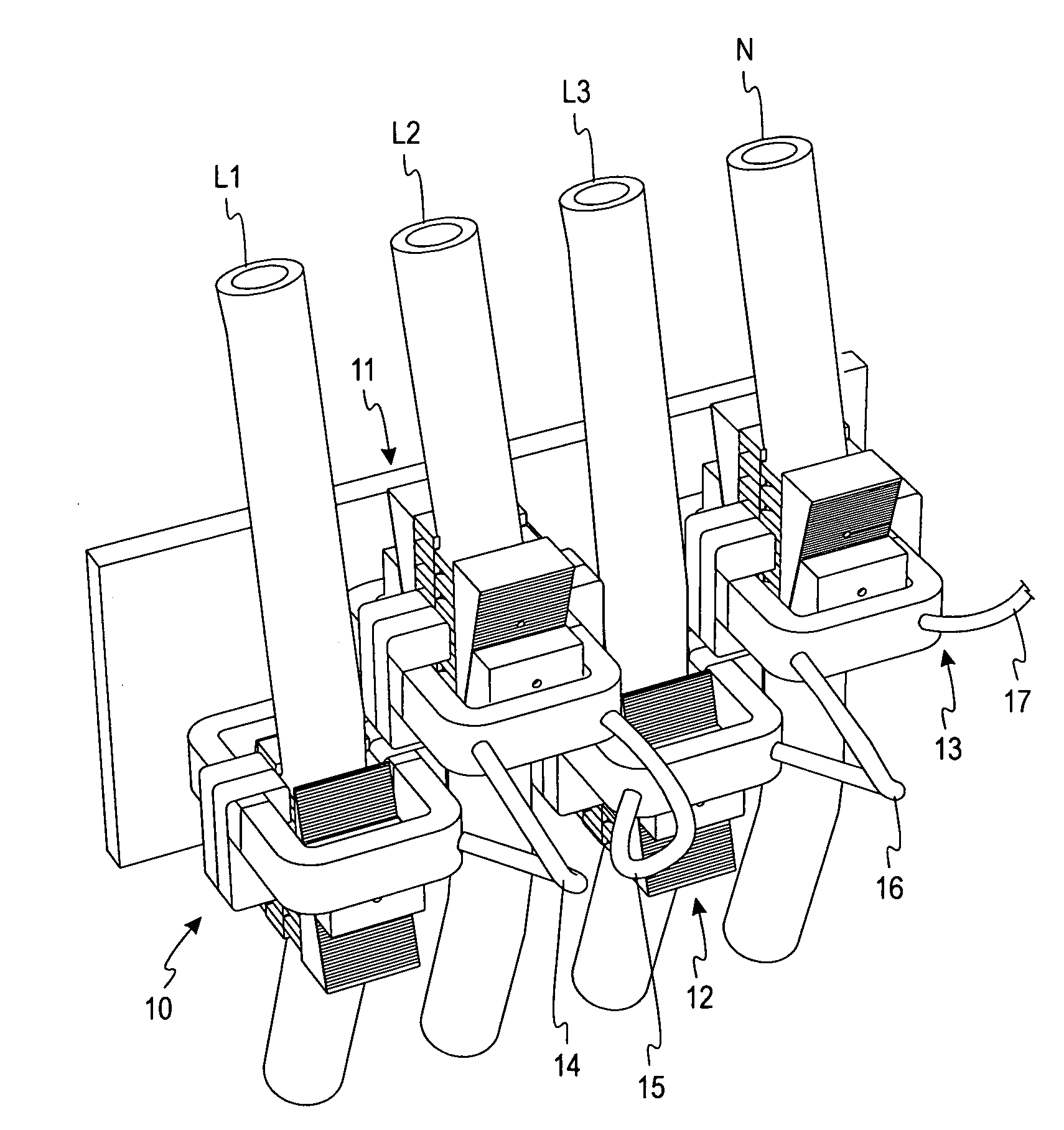
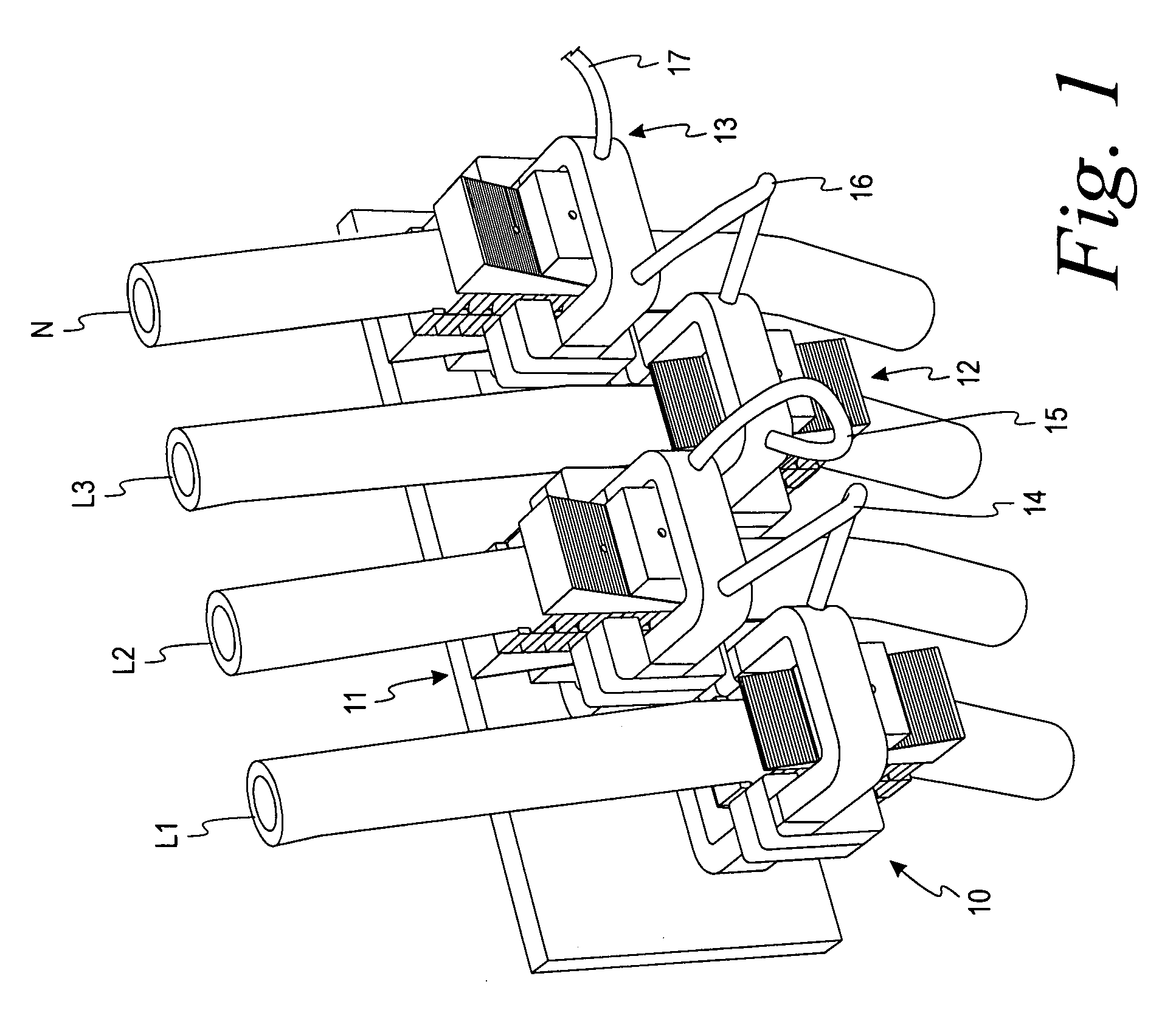
[0026]Turning now to the drawings and referring first to FIG. 1, a set of four identical CVM's 10, 11, 12 and 13 are coupled to the four insulated conductors L1, L2, L3 and N of a three-phase power distribution system. Each CVM 10-13 is clamped tightly around the insulation of one of the power conductors L1-L3 and N so that any current flowing in that conductor is sensed by the CVM, which produces a corresponding current signal for use in a power monitoring system. In addition, each CVM also includes a voltage sensor that produces a corresponding voltage signal for use in the power monitoring system.

[0027]The analog output signals from both the current sensors and the voltage sensors in the CVM are converted to a digital signal in analog-to-digital (“A / D”) converters built into the CVM's 10-13. The resulting digital output signals from the A / D converters can be fed to a processor that executes a series of calculations designed to monitor multiple characteristics of the power being d...


PUM


Abstract

A clamp-on current and voltage module for an electrical power monitoring system that monitors characteristics of power distributed through one or more power conductors includes a current transformer having a core divided into at least two parts so that the core can be installed around a power conductor without cutting the conductor. The transformer produces a current signal corresponding to current passing through the power conductor. A pair of clamping elements fit on opposite sides of the conductor, for gripping the conductor. The transformer core parts and the clamping elements have engaging surfaces that prevent relative movement between the CT enclosure and the power conductor in a direction transverse to the axis of the power conductor. A voltage sensor makes electrical contact with the power conductor and produces a voltage signal corresponding to the voltage on the power conductor.

Description

FIELD OF THE INVENTION[0001]The present invention relates generally to power monitoring systems and particularly to current and voltage modules (“CVM's”) for use in such systems.BACKGROUND OF THE INVENTION[0002]Existing solutions for retrofitting a power monitoring system in an electrical installation, include use of clamp-on current transforms (CTs) with current output of 1 or 5 amperes, requiring the wiring of the CTs, shorting block, voltage input connections, voltage disconnect and voltage protection device. In a three-phase, four-wire circuit, this solution requires more than 30 wires with 61 connection points. Use of clamp-on electronic CT's reduces the safety hazard of the standard CT, eliminating the need for shorting blocks. However, in a three-phase, four-wire configuration, this solution still requires more than 22 wires with 45 connection points. Another limitation of this solution is decreased system accuracy, as the low-voltage-output CT's have lower accuracies than st...

Claims


Application Information

Patent Timeline
Patent Type & Authority Applications(United States)
IPC IPC(8): G01R19/22G01R15/18
CPCG01R15/142G01R15/186
Inventor PEREZ, MARCELO A.
Owner SQUARE D CO
Why Eureka
Try Eureka