Rotation angle detecting device

a detection device and rotation angle technology, applied in the direction of speed measurement using gyroscopic effects, instruments, converting sensor output mechanically, etc., can solve the problem of not being able to detect a rotation angle in such a prior art rotation angle detecting device, and achieve the effect of improving the rotation angle detection

Active Publication Date: 2008-11-20
DENSO CORP +1
View PDF6 Cites 14 Cited by
  • Summary
  • Abstract
  • Description
  • Claims
  • Application Information

AI Technical Summary

Benefits of technology

[0006]Therefore, an object of the invention is to provide an improved rotation angle detecting device that can detec

Problems solved by technology

However, it is impossible for such a prior art rotation angle detecting

Method used


Image

  • Rotation angle detecting device
  • Rotation angle detecting device
  • Rotation angle detecting device

Examples


first embodiment

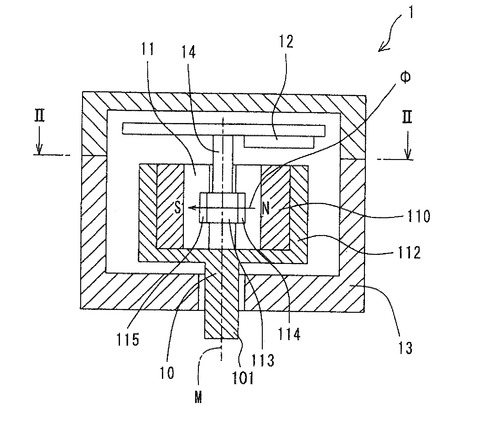
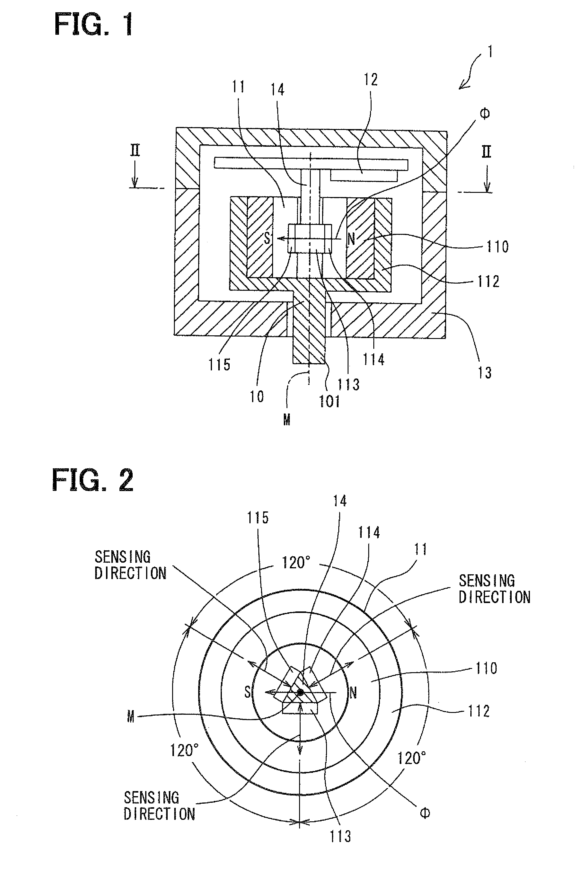
[0023]A rotation angle detecting device 1 according to the invention will be described with reference to FIG. 1-FIG. 4.

[0024]As shown in FIGS. 1 and 2, the rotation angle detecting device 1 includes a signal generator 11, a rotation angle calculating unit 12, a housing 13 and a support member 14.

[0025]The signal generator 11 is comprised of a rotor 10 and three magnetic sensors 113-115. In other words, the signal generator 11 is comprised of the permanent magnet 110, the yoke 112 and the magnetic sensor elements 113-115.

[0026]The rotor 10 is rotatably supported by the housing 13 and includes a permanent magnet 110, a yoke 112 and a rotary shaft 101 connected with a rotating object (not shown). The permanent magnet 110 is a cylindrical member made of ferrite that is magnetized in a direction perpendicular to the rotation axis M of the rotor 10. Accordingly, a magnetic pole N is formed on one portion of the inside surface of the cylindrical permanent magnet 110 and a magnetic pole S i...

second embodiment

[0035]A rotation angle detecting device 2 according to the invention will be described with reference to FIG. 5-FIG. 11.

[0036]As shown in FIG. 5, the rotation angle detecting device 2 includes a shaft 20, a signal generator 23, a rotation angle calculating unit 24, a housing 25 and a support member 26. The signal generator 23 is comprised of a gear 21, a rotor 22 and three magnetic sensors 234-236. The shaft 20 carries the gear 21 at the middle thereof and is connected with a rotating object at one end so as to rotate the gear 21 when the rotating object rotates. The shaft 20 is rotatably supported by the housing 25. The rotor 22 is also rotatably supported by the housing via a sleeve 2331. The rotor 22 includes a cylindrical permanent magnet 230, a cylindrical yoke 232 and a yoke shifting mechanism 233. The cylindrical yoke 232 has gear teeth on the outer periphery thereof in engagement with the gear 21.

[0037]The signal generator 23 generates three output signals, each of which has...


PUM


Abstract

A rotation angle detecting device includes a signal generator, a magnetic rotor and a rotation angle calculating unit that calculates a rotation angle θ of the rotor based on the output signals of the signal generator. The signal generator includes a magnetic rotor that has a permanent magnet and a shaft connectable with the rotating object and at least three magnetic sensor elements disposed in the magnetic field to generate a plurality of output signals when the rotor rotates. The rotation angle calculating unit calculates a first candidate of the rotation angle θ from a first pair of the three output signals, examines whether the first candidate of the rotation angle θ is normal or not and calculates a next candidate of the rotation angle θ from another pair of the three output signals if the first candidate of the rotation angle θ is not normal, examines whether the next candidate of the rotation angle θ is normal or not, repeats the above two steps until a next candidate of the rotation angle θ is judged normal, and outputs one of the first and next candidates of the rotation angle θ as a formal rotation angle if it is judged normal.

Description

CROSS REFERENCE TO RELATED APPLICATION[0001]The present application is based on and claims priority from Japanese Patent Applications 2007-133380, filed May 18, 2007, the contents of which are incorporated herein by reference.BACKGROUND OF THE INVENTION[0002]1. Field of the Invention[0003]The present invention relates to a rotation angle detecting device that detects the rotation angle of a rotating object.[0004]2. Description of the Related Art[0005]JP-A-2003-75108 discloses a prior art rotation angle detecting device that is constructed of a disk-shaped permanent magnet and two or three magnetic sensors. The magnetic sensors are respectively disposed at portions to confront the permanent magnet so as to generate output signals according to the magnetic field strength. A rotation angle of a rotating object is calculated by a certain arithmetic expression based on the output signals of the magnetic sensors. However, it is impossible for such a prior art rotation angle detecting devi...

Claims


Application Information

Patent Timeline
IPC IPC(8): G01B7/30
CPCG01D5/04G01D5/145G01D2205/26G01D2205/22
Inventor HATANAKA, SHINJITAKEDA, KENJIFUKAYA, SHIGETOSHI
Owner DENSO CORP
Why Eureka
Try Eureka