Air suctioning and filtering device having instantly available air suctioning and thermal sensing

a filter device and air suctioning technology, applied in the direction of medical science, surgical instruments for aspiration of substances, surgery, etc., can solve the problems of offensive smoke, high cost, and high risk of surgeons and other operating room sta

Inactive Publication Date: 2008-11-20
INESON LEONARD
View PDF4 Cites 48 Cited by
  • Summary
  • Abstract
  • Description
  • Claims
  • Application Information

AI Technical Summary

Benefits of technology

This patent describes a new device that helps remove smoke during surgeries caused by electric tools. It has three main components: an intake for collecting air, a filtration unit for cleaning the air, and a vacuum machine for removing the purified air. The device can adjust how much air it takes in based on the needs of the patient and the type of surgery they are having. By improving this process, researchers hope to make smoking control easier and safer during medical procedures.

Problems solved by technology

The technical problem addressed in this patent is the delay in starting the suctioning of surgical smoke from the electrosurgical pencil, which can result in the plume of smoke wafting towards the surgeon and others in the operating room. The patent aims to provide an air suctioning and filtering device that overcomes this delay and ensures the efficient evacuation of smoke plume.

Method used


Image

  • Air suctioning and filtering device having instantly available air suctioning and thermal sensing
  • Air suctioning and filtering device having instantly available air suctioning and thermal sensing
  • Air suctioning and filtering device having instantly available air suctioning and thermal sensing

Examples


Embodiment Construction

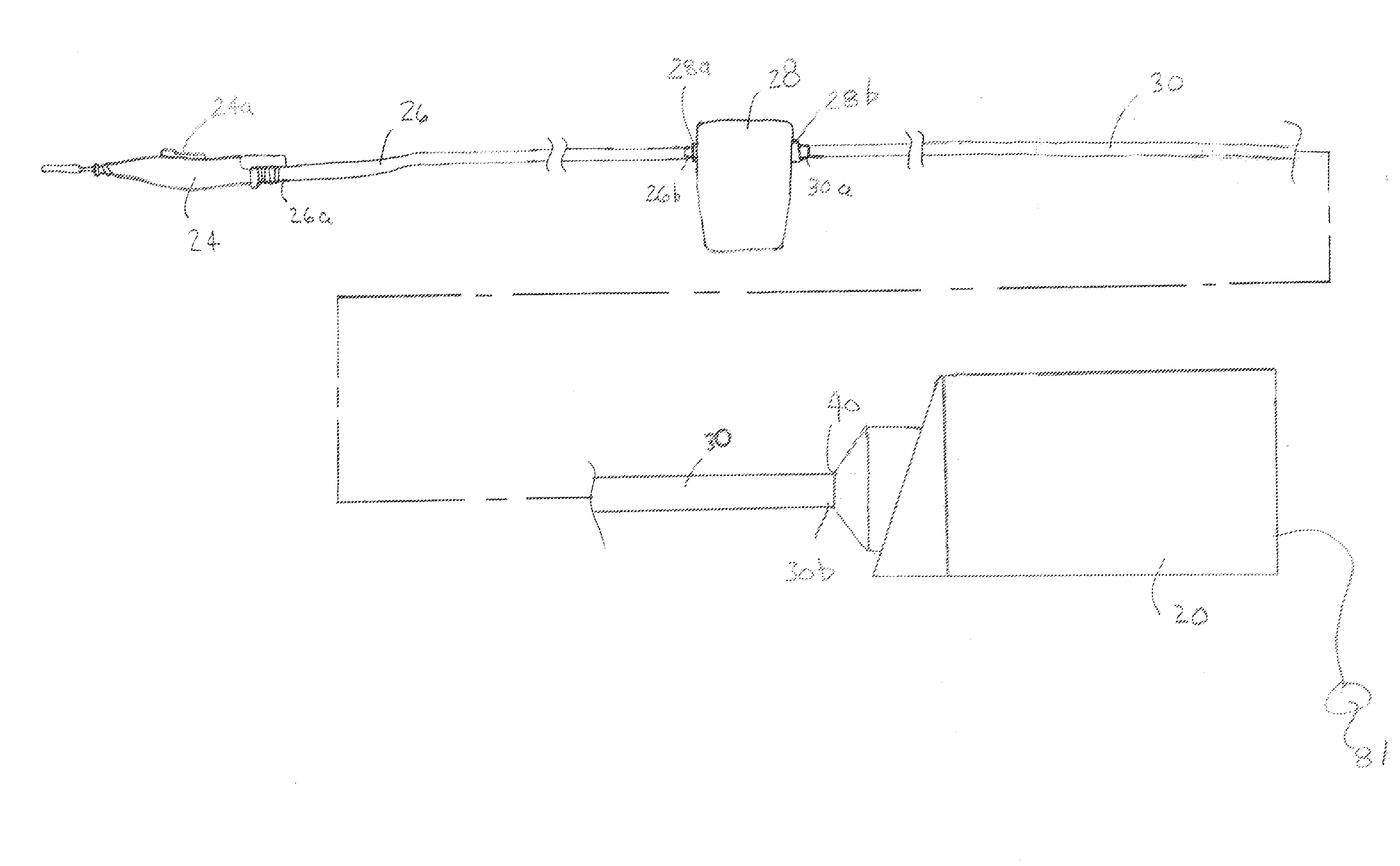
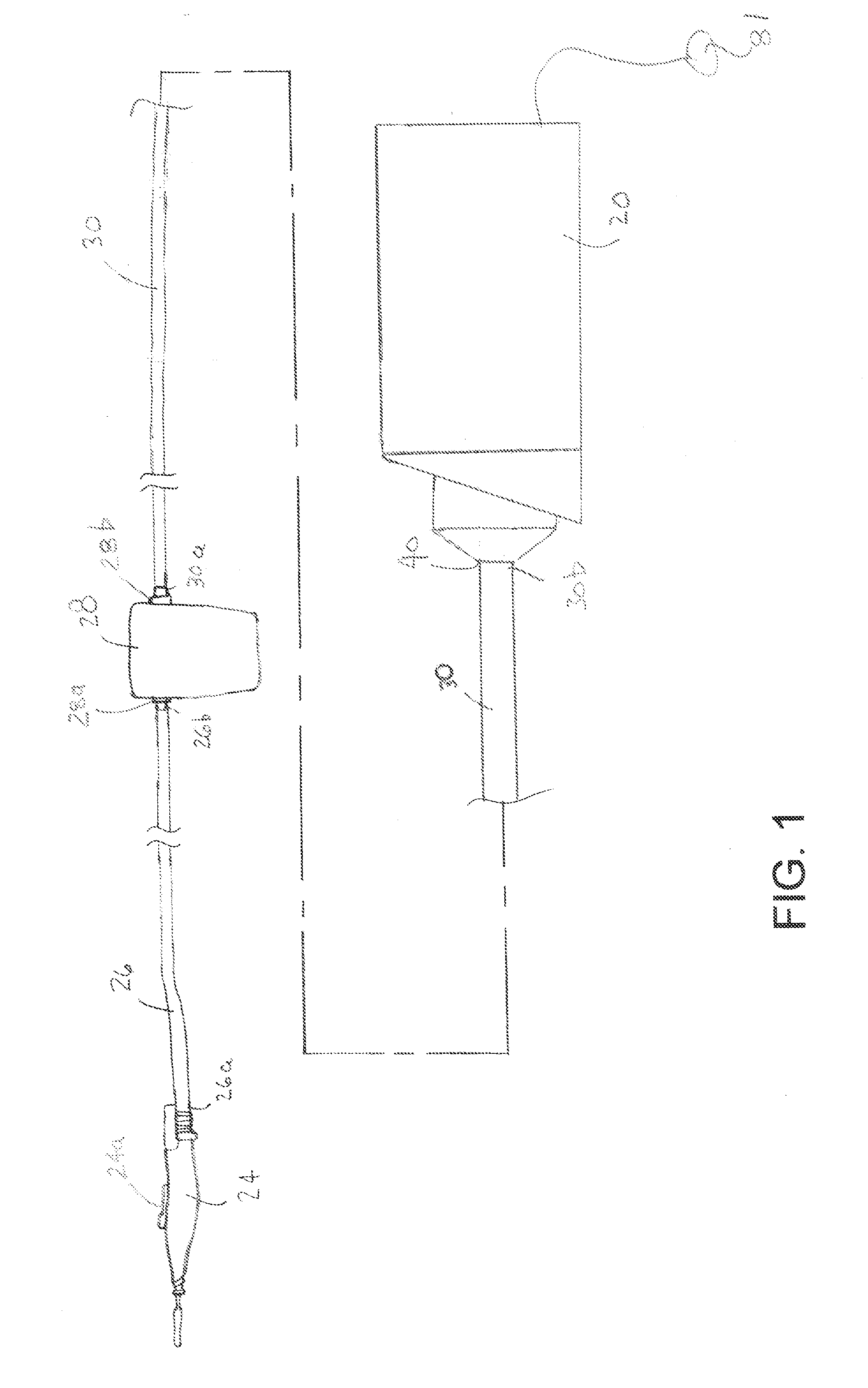
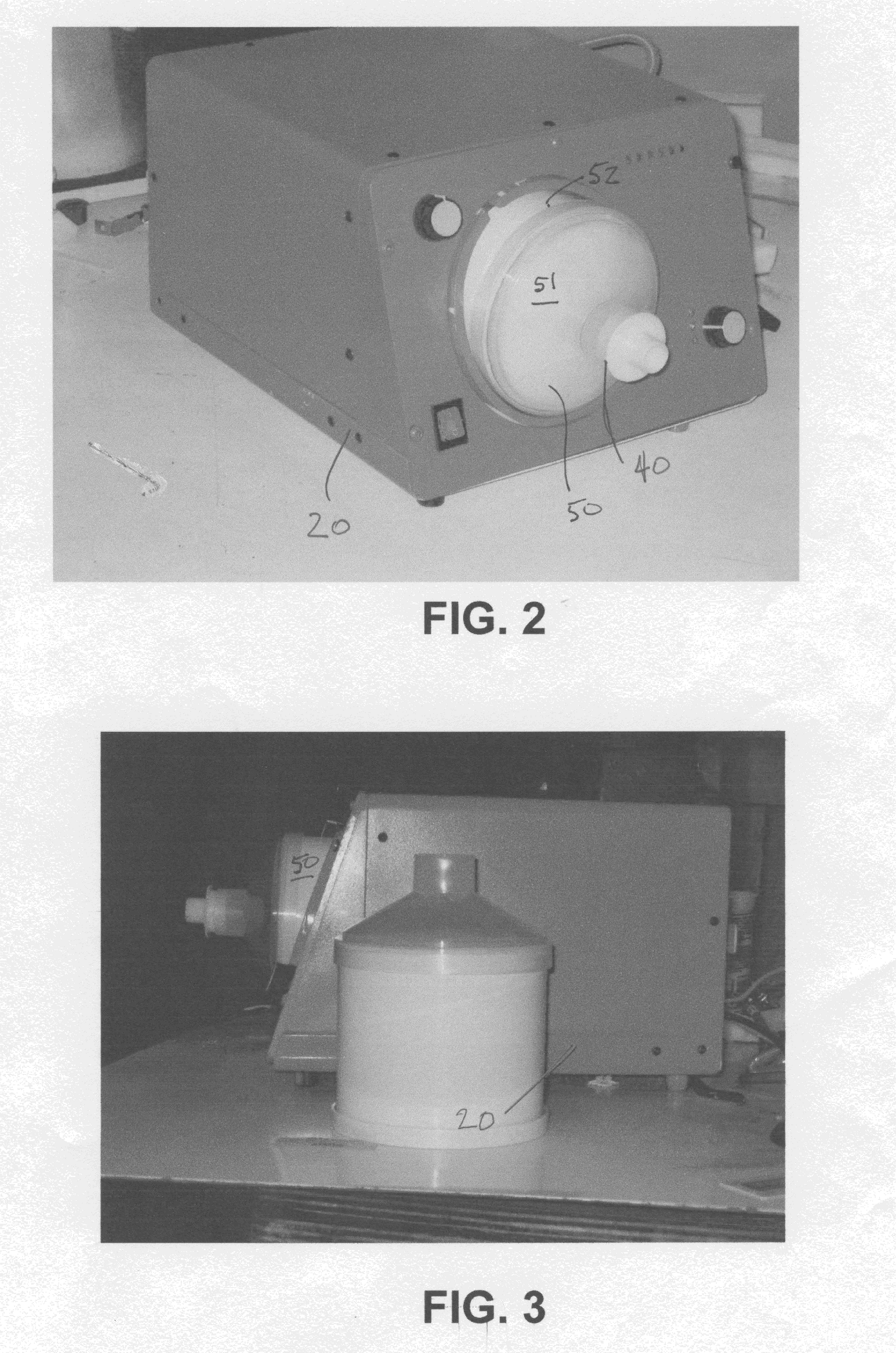
[0021]Reference will now be made to FIGS. 1 through 8, which show a preferred embodiment of the air suctioning and filtering device of the present invention, as indicated by general reference numeral 20. The air suctioning and filtering device 20 is for use in an surgery plume evacuation system, as indicated by the general reference numeral 22 in FIG. 1. The surgery plume evacuation system 22 includes an electrosurgical pencil 24, a first flexible tube 26, a suction collection container 28 (which is optional and may or may not be used), a second flexible tube 30, and the air suctioning and filtering device 20. The intake end 26a of the first flexible tube 26 is connected to the electrosurgical pencil 24 and the delivery end 26b of the first flexible tube 26 is connected to the inlet nozzle 28a of the suction collection container 28 to permit delivery of air, smoke, moisture, liquid, and particulate matter from the electrosurgical pencil 24 to the suction collection container 28. The...


PUM


Abstract

An air suctioning and filtering device for use in an surgery plume evacuation system comprises a suction inlet, a filter connected in fluid communication with the suction inlet, a connector pipe connected in fluid communication with the filter, and a vacuum fan connected in fluid communication with the connector pipe to suction air into the suction inlet, through the filter, and through the connector pipe. An air by-pass inlet having a shutter valve mounted thereon permits air to be suctioned to the source of suction without ingressing into the suction inlet, when the shutter valve is in a standby position. A much smaller amount of air is suctioned through the auction inlet. In a full suctioning position, with the shutter valve closed over the air by-pass inlet, all of the air is suctioned into the suction inlet from an electrosurgical pencil.

Description


Claims


Application Information

Patent Timeline
Owner INESON LEONARD
Why Eureka
Try Eureka