Illuminated Directional Laser Probe

a laser probe and illumination technology, applied in the field of microsurgical equipment, can solve the problems of inability to achieve optimal delivery of illumination light and laser light to the surgical site at the anterior or forward portion of the retina, and the limitations of prior art illumination instruments and laser instruments described abov

Active Publication Date: 2008-11-20
SYNERGETICS
View PDF34 Cites 62 Cited by
  • Summary
  • Abstract
  • Description
  • Claims
  • Application Information

AI Technical Summary

Benefits of technology

[0022]Thus, the illuminated directional laser probe of the invention enables supplying both illumination light and laser light to a surgical site in the interior of an eye through only a single incision in the eye. The probe of the invention also provides the ability to direct the illumination light and laser light simultaneously to the interior of the eye, enabling accessing a surgical site on an anterior portion or forward portion of the eye interior.

Problems solved by technology

The above-described ophthalmic surgery procedures are disadvantaged in that they require at least two incisions in the eye, increasing the trauma to the eye.
Furthermore, the prior art illumination instrument and the prior art laser instrument described above are limited to directing illumination light and laser light to only the posterior area of the eye interior.
In using instruments of this type, the optimal delivery of illumination light and laser light to a surgical site at an anterior or forward portion of the retina cannot be achieved.

Method used


Image

  • Illuminated Directional Laser Probe
  • Illuminated Directional Laser Probe
  • Illuminated Directional Laser Probe

Examples


first embodiment

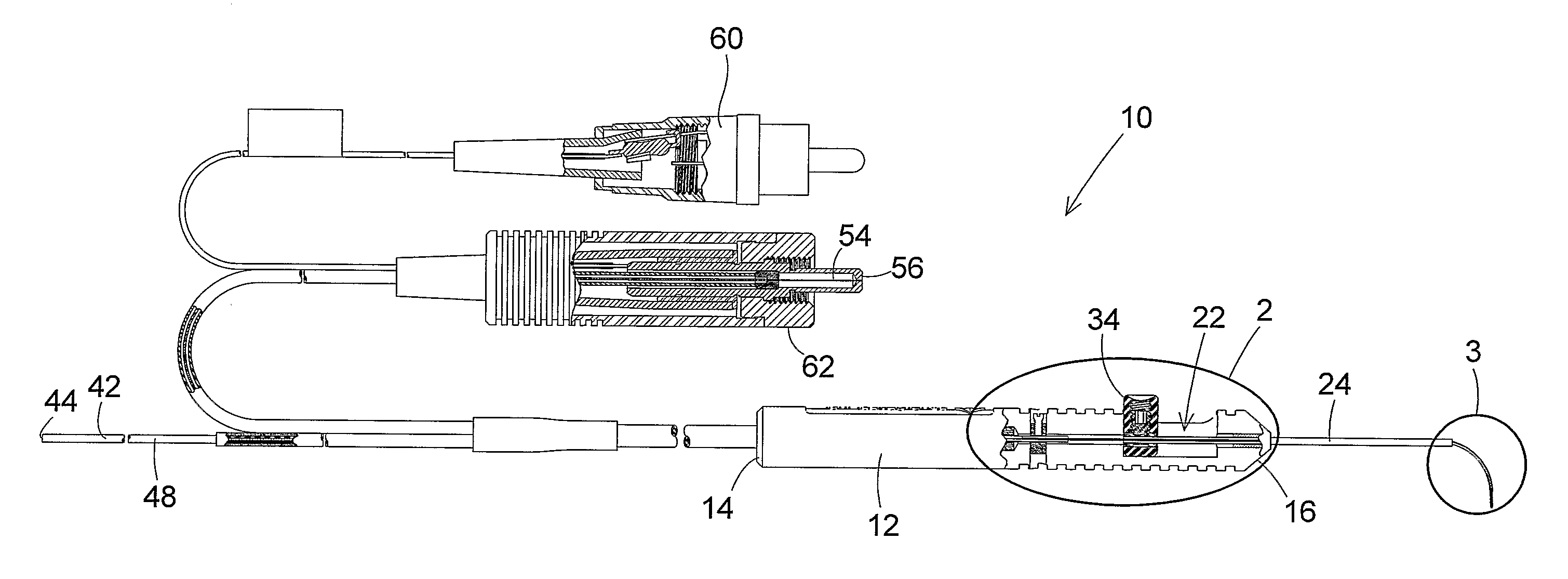
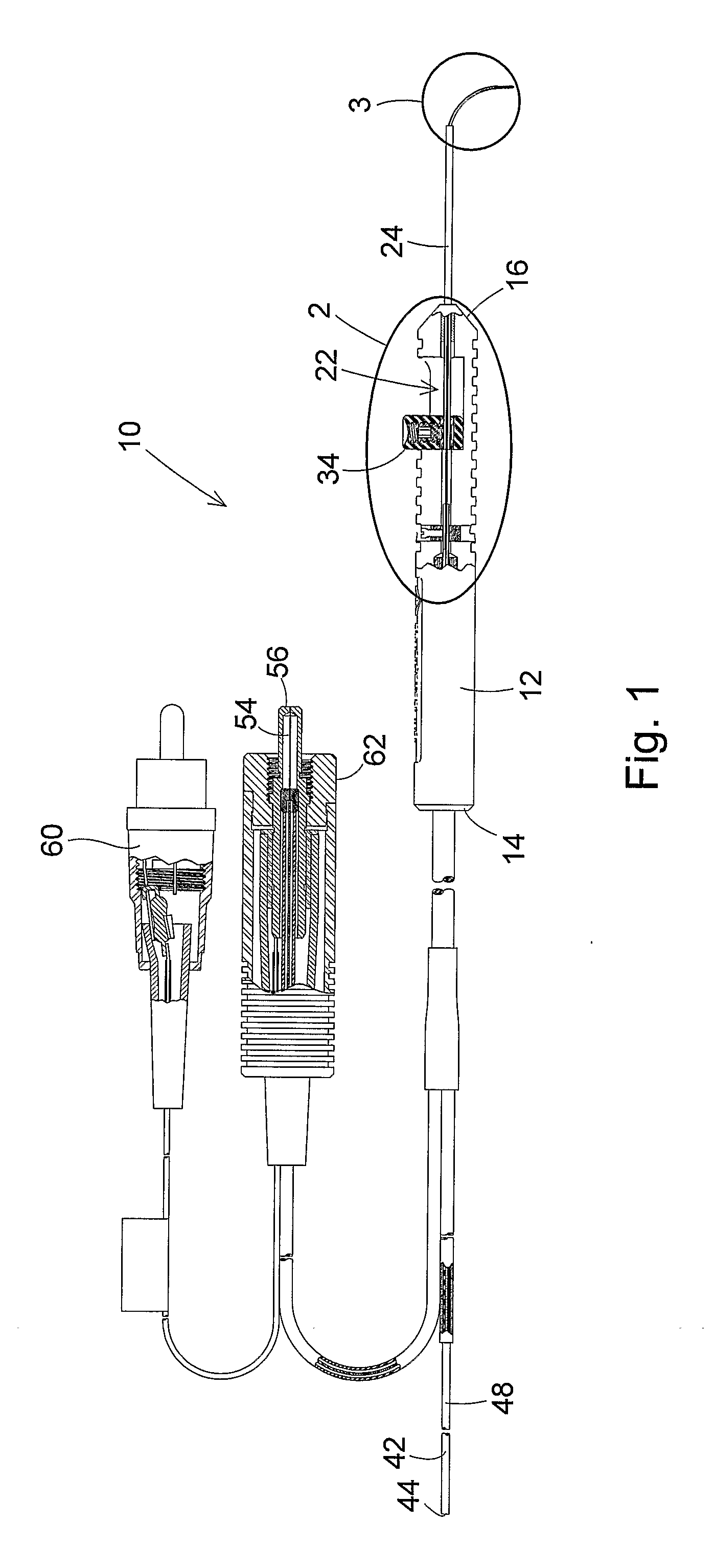
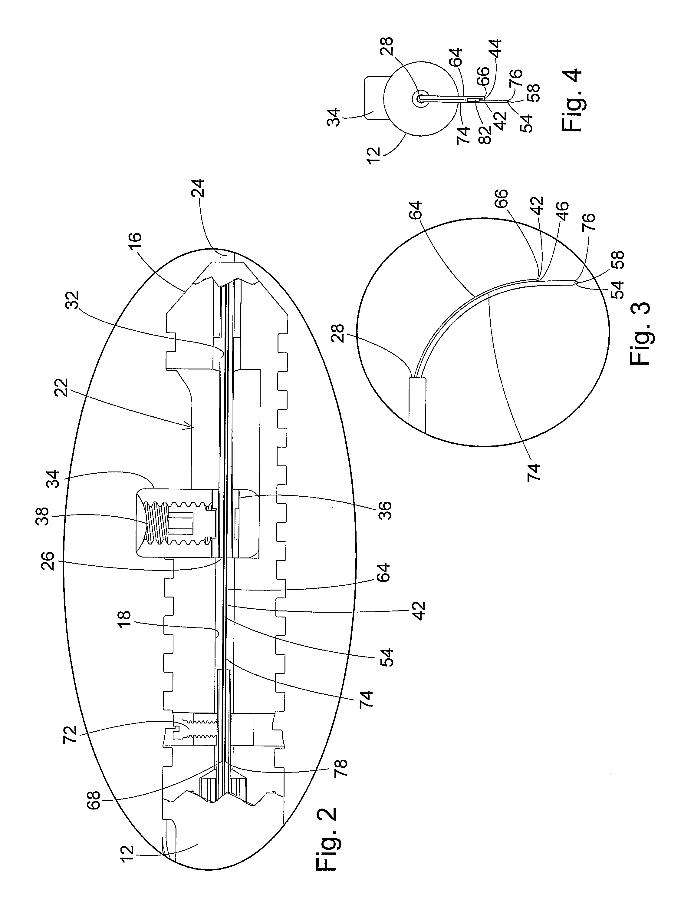
[0051]In the operation of this first embodiment of the probe 10, movement of the finger actuator 34 in the rearward direction through the handle cavity 22 causes the tip distal end 28 to move toward the handle distal end 16. This causes the distal end portions of the illumination optic fiber 42 contained in the first tube 64 and the laser optic fiber 54 contained in the second tube 74 to be extended from the tip distal end 28. As the first tube 64 and second tube 74 extend outwardly from the tip distal end 28, the curved configurations of the tubes cause the illumination optic fiber 42 and the laser optic fiber 54 to gradually bend together toward the bent or curved configurations of the fibers shown in FIGS. 1, 3, and 4.

[0052]Movement of the finger actuator 34 in the forward direction through the handle cavity 22 causes the tip 24 to be extended from the handle distal end 16. This causes the first tube 64 containing the illumination optic fiber 42 and the second tube 74 containing ...

second embodiment

[0055]The primary difference between the probe 90 shown in FIGS. 8-15 and the previously described probe 10 is that the first tube 64 and second tube 74 are absent from the probe 90. Instead, a single tube 92 surrounds and contains portions of the illumination optic fiber 42′ and the laser optic fiber 54′ adjacent the respective distal ends 46′, 58′ of the two fibers. The single tube 92 has a length with opposite proximal 94 and distal 96 ends. In the preferred embodiment of the invention, the single tube 92 is constructed of a resilient shape memory material, such as nitinol. The exterior dimension of the single tube 92 is just large enough to extend around and connect the illumination optic fiber 42′ and the laser optic fiber 54′ side by side, and still slide through the interior bore 32′ of the tip 24′. As in the first tube 64 and second tube 74 of the first described embodiment of the probe, the single tube 92 has a bent or curved configuration adjacent the tube distal end 96. T...


PUM


Abstract

An ophthalmic surgery illuminated directional laser probe has a handle and a rigid tubular tip projecting from the handle, and has an illumination optic fiber and a laser optic fiber that extend through the handle and the tip. A mechanism on the handle is operable to extend distal ends of the illumination optic fiber and the laser optic fiber from the distal end of the instrument tip, and to retract the distal ends of the illumination optic fiber and the laser optic fiber back into the interior of the tip. At least one of the distal ends of the illumination optic fiber and the laser optic fiber is held in a curved configuration. The distal ends of the illumination optic fiber and the laser optic fiber are secured to each other, whereby both the illumination optic fiber and the laser optic fiber curve into a bent configuration as the distal ends of the illumination optic fiber and the laser optic fiber are extended from the distal end of the instrument tip.

Description

[0001]This patent application claims the benefit of Provisional Patent Application Ser. No. 60 / 707,475, filed Aug. 11, 2005.BACKGROUND OF THE INVENTION[0002](1) Field of the Invention[0003]The present invention pertains to a microsurgical apparatus primarily used in ophthalmic surgery procedures. In particular, the invention pertains to an illuminated directional laser probe having a handle and a rigid tubular tip projecting from the handle, and having an illumination optic fiber and a laser optic fiber that extend through the handle and the tip. A mechanism on the handle is operable to cause distal ends of the illumination optic fiber and the laser optic fiber to be extended from the distal end of the tubular tip, and to cause the distal ends of the illumination optic fiber and the laser optic fiber to be retracted back into the tubular tip. At least one of the distal ends of the illumination optic fiber and the laser optic fiber is held in a curved configuration. The distal ends o...

Claims


Application Information

Patent Timeline
Patent Type & Authority Applications(United States)
IPC IPC(8): A61B1/07
CPCA61B18/22A61B2018/00196A61B2019/5206A61B2090/306A61B2018/2288A61F9/008
Inventor SCHELLER, GREGG D.AULD, MICHAEL D.NADOLSKI, TIMOTHY J.
Owner SYNERGETICS
Why Eureka
Try Eureka