Pedicle Screw and Rod System

a technology which is applied in the field of pedicle screw and rod system for spinal fusion surgery, can solve the problems of nerve root injury, more surgery, and significant post-operative pain and discomfort for patients

Active Publication Date: 2008-11-20
MI4SPINE
View PDF15 Cites 119 Cited by
  • Summary
  • Abstract
  • Description
  • Claims
  • Application Information

AI Technical Summary

Benefits of technology

[0014]In accordance with the teachings of the present invention, a pedicle screw and rod system is disclosed that has particular application for spinal fusion surgery. The system includes pedicle screws having ball-shaped heads that are threaded through pedicles of adjacent vertebra into the vertebral body. The system also includes two cannulated posts having a head portion with a planar portion and an opening for accepting the head of the pedicle screw in a secure and multi-axial engagement. The system further includes a tube portion that is coupled to the head portion and extends above the patient's skin. The system also includes a lordotic slotted rod that is slid down the tube portions to be positioned on top of the head portions of the posts so that the planar portions are locked within the slot. Bolts are then slid down the tube portions and are threaded to a threaded portion on the planar portion. A weakened portion of the tube portion is provided just above the head portion, so that when the post is properly torqued, the tube portion will break at the weakened portion, and can be removed from the patient.

Problems solved by technology

This results in significant muscle and ligamentous damage resulting in significant post-operative pain and discomfort for patients and often extending hospital stays.
Recovery times can be extended and additional problems at adjacent levels of the spine can ultimately result in more surgery.
Gentle taps with a mallet cause the Jamshidi needle to be advanced through the pedicle, making sure not to cross the medial border of the pedicle, which can result in nerve root injury, until the junction between the pedicle base and the vertebral body is reached.

Method used


Image

  • Pedicle Screw and Rod System
  • Pedicle Screw and Rod System
  • Pedicle Screw and Rod System

Examples


Embodiment Construction

[0024]The following discussion of the embodiments of the invention directed to a pedicle screw and rod system for spinal fusion surgery is merely exemplary in nature, and is in no way intended to limit the invention or its applications or uses. For example, the pedicle screw and rod system of the invention has particular application for spinal fusion surgery. However, the pedicle screw system of the invention may have other applications.

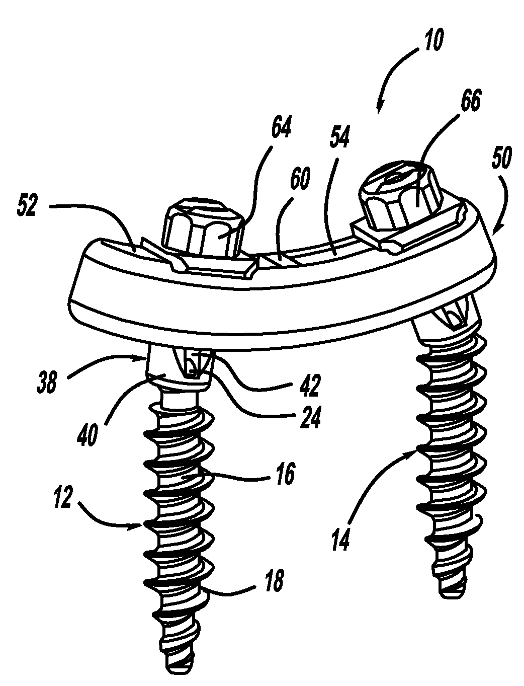
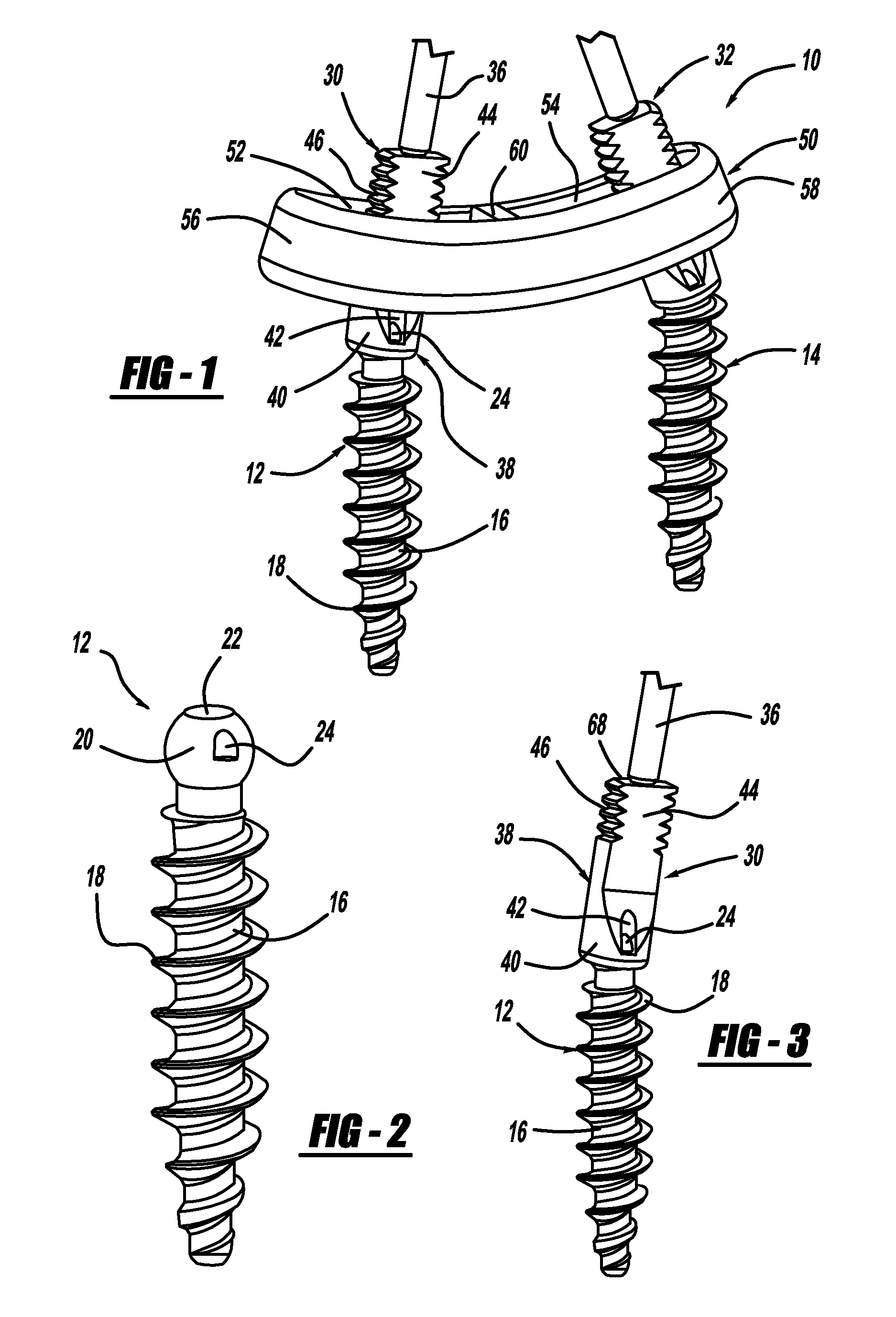
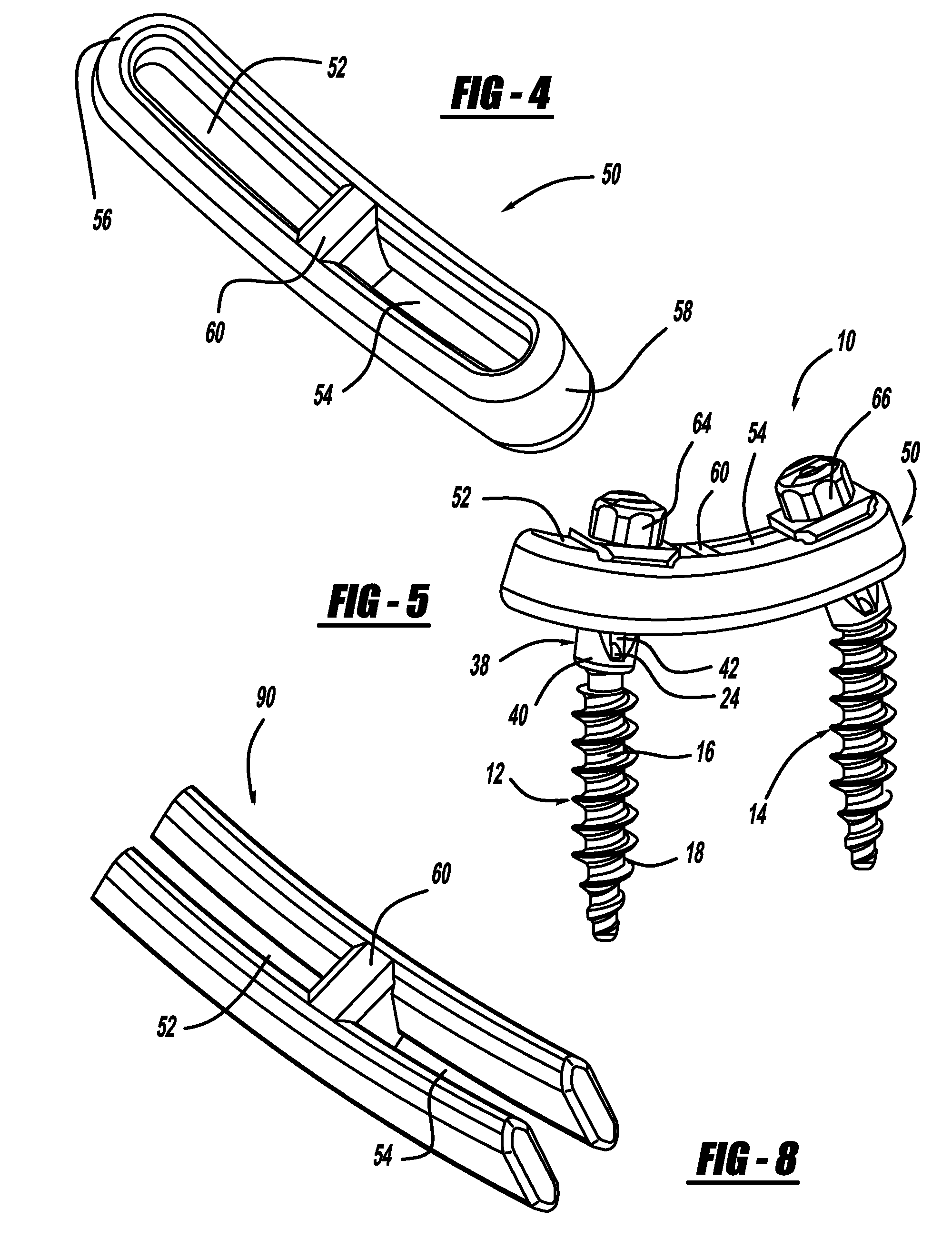
[0025]FIG. 1 is a perspective view of a pedicle screw and rod system 10, according to an embodiment of the present invention. The system 10 includes a pair of pedicle screws 12 and 14, where a perspective view of the pedicle screw 12 is shown in FIG. 2. The pedicle screw 12 includes a body portion 16 having outer threads 18 and a ball-shaped head 20. A channel 22 extends through the head 20 and the body portion 16 making the pedicle screw cannulated. A pair of opposing tabs 24 is formed to the head 20 for reasons that will become apparent from the di...


PUM


Abstract

A pedicle screw and rod system that has particular application for spinal fusion surgery. The system includes pedicle screws having ball-shaped heads that are threaded through pedicles of adjacent vertebra into the vertebral body. The system also includes two cannulated posts having a head portion with a planar portion and an opening for accepting the head of the pedicle screw in a secure and multi-axial engagement. The system further includes a tube portion that is coupled to the head portion and extends above the patient's skin. The system also includes a lordotic slotted rod that is slid down the tube portions to be positioned on top of the head portions of the posts so that the planar portions are locked within the slot. Bolts are then slid down the tube portions and are threaded to a threaded portion on the planar portion.

Description

CROSS-REFERENCE TO RELATED APPLICATIONS[0001]This application claims the benefit of priority to Provisional Patent Application Ser. No. 60 / 912,872, filed Apr. 19, 2007 and titled “Pedicle Screw and Rod System”.BACKGROUND OF THE INVENTION[0002]1. Field of the Invention[0003]This invention relates generally to a pedicle screw and rod system for spinal fusion surgery and, more particularly, to a pedicle screw and rod system for spinal fusion surgery where the rod includes a slot that holds a planar portion of a head of opposing post members.[0004]2. Discussion of the Related Art[0005]The human spine includes a series of vertebrae interconnected by connective tissue referred to as disks that act as a cushion between the vertebrae. The disks allow for movement of the vertebrae so that the back can bend and rotate.[0006]Spinal fusion is a surgical procedure that fuses two or more vertebrae together using bone grafts and / or other devices. Spinal fusion is a commonly performed procedure for...

Claims


Application Information

Patent Timeline
Patent Type & Authority Applications(United States)
IPC IPC(8): A61B17/70A61B17/04
CPCA61B17/7007A61B17/701A61B17/7037A61B17/8685
Inventor PEREZ-CRUET, MIGUELANGELO J.PEPPER, JOHN R.
Owner MI4SPINE
Why Eureka
Try Eureka