Agricultural working machine

Active Publication Date: 2008-11-20
CLAAS SELBSTFAHRENDE ERNTEMASCHINEN GMBH
View PDF3 Cites 31 Cited by
  • Summary
  • Abstract
  • Description
  • Claims
  • Application Information

AI Technical Summary

Benefits of technology

[0008]The object of the present invention, therefore, is to provide a display unit with assigned input means

Problems solved by technology

The disadvantage of a display structure of this type is the fact that the driver of an agricultural working machine is limited in terms of the information displayed—the driver is only shown the operating state or the out-of-operation state of the working units shown.
In this case, operators with little or no experience often become overwhelmed due to the large number of operating parameters shown in the display area, and they must repeatedl

Method used


Image

  • Agricultural working machine
  • Agricultural working machine
  • Agricultural working machine

Examples


Example

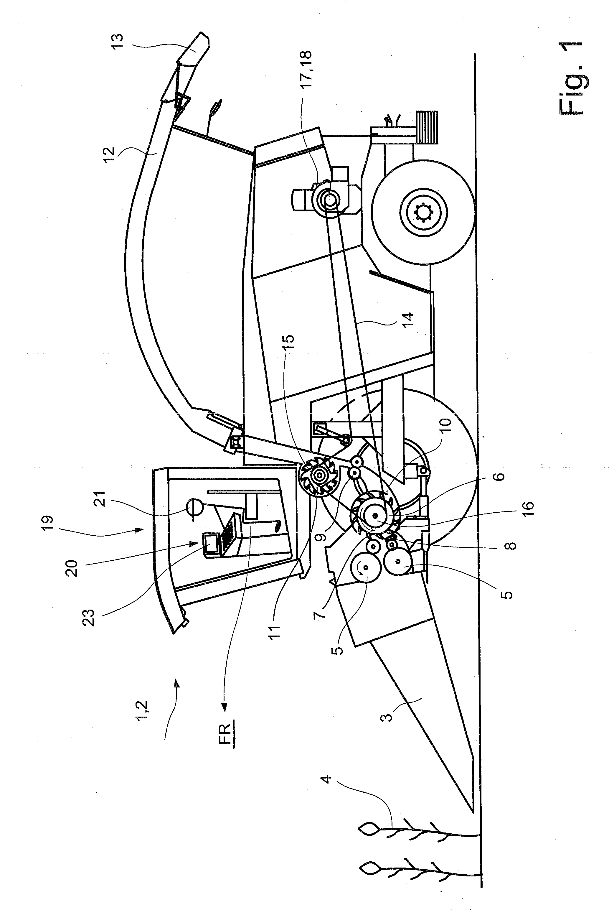
[0022]FIG. 1 shows a sectional side view of an agricultural harvesting machine 2 designed as a self-propelled forage harvester 1 with different working units, which will be described in greater detail below. A front attachment 3 is assigned to forage harvester 1 in the front, as viewed in the direction of travel FR, which picks up crop material 4 during the working operation of forage harvester 1, and which may fragmentize it, then guide it to downstream intake and compression rollers 5. Intake and compression rollers 5 guide crop material 4 to downstream, rotating chopper drum 6, the cutter blade 7 of which fragmentizes crop material 4 at a shear bar 8.

[0023]Fragmentized crop material 4 is subsequently transferred to a post-fragmentation device 9, which pounds the crop grains, e.g., corn, and transfers them via a conveyer chute 10 to a post-accelerator 11. Post-accelerator 11 accelerates fragmentized crop material 4 and conveys it—via a horizontally and vertically displaceable uppe...


PUM


Abstract

An agricultural working or harvesting machine has at least one working unit and a driver's cab in which, in a basic electronic display area of a display unit, several machine and/or crop material parameters set up in different functionality windows are visualized. The machine and/or crop material parameters set up in the functionality windows are activated and controlled using an operating device, and, in the working mode at least, at least one additional display area that includes the functionality window superimposed on the basic display area is displayable in the display unit, it being possible to control and activate the at least one functionality window of the additional display area using at least one separate operating device.

Description

CROSS-REFERENCE TO A RELATED APPLICATION[0001]The invention described and claimed hereinbelow is also described in German Patent Application DE 10 2007 022 899.8 filed on May 14, 2007. This German Patent Application, subject matter of which is incorporated herein by reference, provides the basis for a claim of priority of invention under 35 U.S.C. 119(a)-(d).BACKGROUND OF THE INVENTION[0002]The present invention relates to an agricultural working machine with an electronic display unit.[0003]Publication DE 198 05 133 A1 discloses an electronic display and / or operating device with a display and status display fields, in the case of which the use of certain symbols makes it possible for the operating state or out-of-operation state of different working units to be displayed in the same display field. According to the invention, the out-of-operation state of a working unit is indicated, e.g., by the symbol of a line passing through the particular working unit, the line being located ab...

Claims


Application Information

Patent Timeline
IPC IPC(8): G01D7/00
CPCA01D41/12A01D43/08Y10S56/15
Inventor JEPPE, ECKEHARDLAING, REINHARD
Owner CLAAS SELBSTFAHRENDE ERNTEMASCHINEN GMBH
Why Eureka
Try Eureka