Check patentability & draft patents in minutes with Patsnap Eureka AI!

Relay server, relay communication system, and communication device

Active Publication Date: 2008-11-20
MURATA MASCH LTD
View PDF56 Cites 45 Cited by
  • Summary
  • Abstract
  • Description
  • Claims
  • Application Information

AI Technical Summary

Benefits of technology

[0012]The invention is contrived to solve the above-mentioned problem. An object of the invention is to provide a relay communication system which can be easily operated and which can allow a terminal to share and operate a resource with a necessary opposite terminal even when the terminals are connected to different LANs and managed under different protocols, and a relay server used for the system. Another object of the invention is to provide a dynamic relay communication system which is expansible and flexible and which can cope with movement or the like of resources.
[0037]In the relay communication system employing the relay server according to the invention, among the client terminals connected to different LANs, the respective client terminals can operate a resource held by another client terminal over the WAN as if they hold the resource. The client terminals can form a group with necessary opposites so as to share the resources as needed. Even when the resources are changed due to deletion and the like, the information on the resources is automatically updated. Accordingly, the client terminals can dynamically cope with the deletion of the resources and the like.

Problems solved by technology

However, such a type of system tends to be stiff because a network is virtually constructed.
Accordingly, it is not easy to construct an expansible and flexible system and the suggested systems have both merits and demerits in function, cost, and the like.
However, when a communication system extends between plural LANs over a WAN, it is not possible to easily cope with such intention that plural terminals share resources such as folders or files or a file retained by a terminal is deleted by a different terminal.
The resources retained by the terminals vary endlessly due to deletion or movement, but it is not easy to dynamically cope with such a variation.
Software for accessing a certain system should be introduced into terminals disposed in the system, but appropriate software is not available.
Accordingly, it is not easy to share a resource with a necessary opposite as needed.

Method used


Image

  • Relay server, relay communication system, and communication device
  • Relay server, relay communication system, and communication device
  • Relay server, relay communication system, and communication device

Examples


first embodiment

Entire Configuration of Relay Communication System

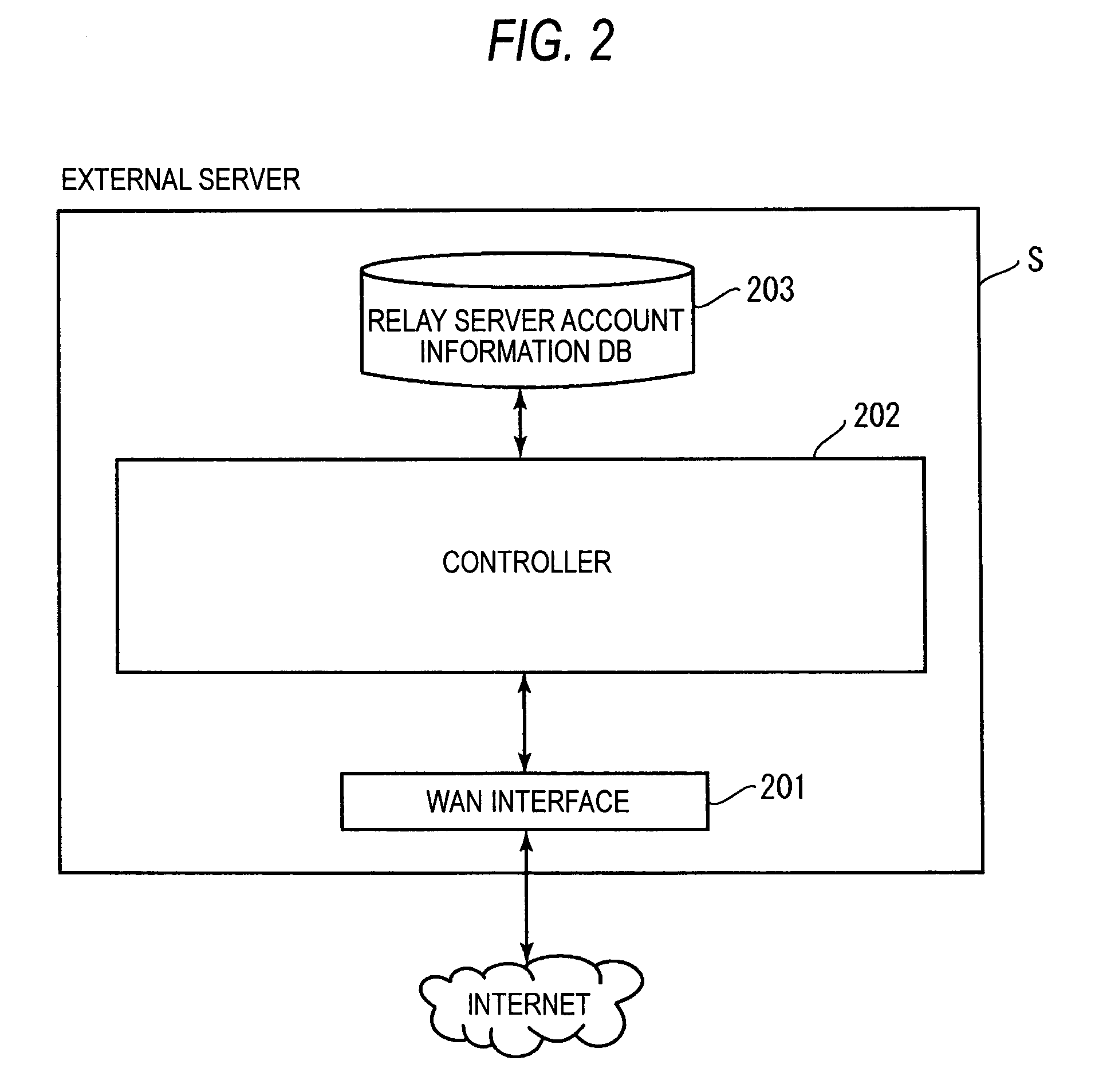
[0074]Hereinafter, a first embodiment of the invention will be described with reference to the drawings. FIG. 1 illustrates an entire configuration of a relay communication system according to the first embodiment. As shown in FIG. 1, the relay communication system includes plural LANs connected to a WAN. The relay communication system includes an external server S, relay servers R, client terminals T, and file servers F. Although the external server S is used in this embodiment, the relay servers R may directly communicate with each other without using the external server S.

[0075]In this embodiment, a system using a session initiation protocol (SIP) as a communication protocol between the external server S and the relay servers R in the WAN and between the relay server R and the client terminals T in the respective LANs is exemplified. However, protocols other than the SIP may be used as a communication protocol between the servers ...

second embodiment

Entire Configuration of Relay Communication System

[0177]A second embodiment of the invention will be described now. The second embodiment is similar to the first embodiment in configurations of a relay communication system, an external server S, a relay server R, and a file server F, but the second embodiment is different from the first embodiment in configuration of a client terminal T.

[0178]FIG. 19 is a functional block diagram illustrating a client terminal T. The client terminal T according to this embodiment further includes a display unit 605 in addition to the constituent elements of the client terminal T according to the first embodiment. The display unit 605 displays relay group information 100 shown in FIG. 20 and the like and shared resource information 120 shown in FIG. 21 and the like.

Display Screen for Relay Group Information and Shared Resource Information

[0179]A flow of processes of the client terminal T in the relay communication system will be described with refere...

third embodiment

Entire Configuration of Relay Communication System

[0207]A third embodiment of the invention will be described now. The third embodiment is similar to the second embodiment in configurations of a relay communication system, an external server S, a client terminal T, and a file server F, but the third embodiment is different from the second embodiment in configuration of a relay server R.

[0208]FIG. 26 is a functional block diagram illustrating a relay server R. The relay server R according to this embodiment further includes a log information database (DB) 507 in addition to the constituent elements f the relay server R according to the second embodiment. The log information DB 507 is a database for managing operation details relayed by the relay servers R as log information.

Resource Operation Details stored as Log Information

Entire Summary of Resource Operation Details

[0209]Resource operation details according to this embodiment will be described with reference to FIGS. 27 to 29. Onl...


PUM


Abstract

A relay server that is connected to a LAN and that can communicate with a relay server of a different LAN, includes: an account information registering unit that stores account information including information on client terminals connected to the LAN; a relay group information registering unit that stores relay group information including information on a group of relay servers permitting access to each other; and a shared resource information registering unit that stores shared resource information including information on resources and information on the client terminals sharing the resources, wherein when an operation command for a resource, which can be operated by a client terminal connected to the different terminal, is received from the client terminal stored in the account information registering unit based on the shared resource information, the operation of the resource is relayed on the basis of the relay group information.

Description

CROSS-REFERENCE TO RELATED APPLICATIONS[0001]This application claims priority under 35 U.S.C. 119 to Japanese Patent Application No. 2006-316815, filed on Nov. 24, 2006, No. 2006-327158, filed on Dec. 4, 2006, and No. 2006-335512, filed on Dec. 13, 2006, which applications are hereby incorporated by reference in their entirety.BACKGROUND OF THE INVENTION[0002]1. Field of the Invention[0003]The present invention relates to a relay server and a relay communication system which can enable communications with terminals in a different local area network (LAN) over a wide area network (WAN), and more particularly, to a technology of allowing a terminal in a LAN to operate resources retained by a terminal in a different LAN.[0004]2. Description of the Related Art[0005]A communication technology called a virtual private network (VPN) is known. By using this communication technology, it is possible to use a remote LAN like a directly connected network. For example, terminals connected to LAN...

Claims


Application Information

Patent Timeline
IPC IPC(8): G06F15/16
CPCH04L12/4604H04L67/104H04L67/1063H04L67/28H04L67/288H04L67/56
Inventor TANIMOTO, YOSHIFUMI
Owner MURATA MASCH LTD
Features
  • R&D
  • Intellectual Property
  • Life Sciences
  • Materials
  • Tech Scout
  • Unparalleled Data Quality
  • Higher Quality Content
  • 60% Fewer Hallucinations
Learn More