Cyclonic Separator and Method for Degassing a Fluid Mixture

a cyclonic separator and fluid mixture technology, applied in the direction of liquid degasification, separation process, reversed direction vortex, etc., can solve the problems of large equipment pieces and limited separation efficiency

Active Publication Date: 2008-11-27
SHELL OIL CO
View PDF12 Cites 16 Cited by
  • Summary
  • Abstract
  • Description
  • Claims
  • Application Information

AI Technical Summary

Benefits of technology

[0021]a vortex tube having a throat section in which the fluid mixture is accelerated such that the static pressure of the fluid mixture is decreased and vaporizable components evaporate into a gaseous phase;

Problems solved by technology

A disadvantage of the latter group of known cyclonic separators is that they generally are large pieces of equipment and have a limited separation efficiency.

Method used


Image

  • Cyclonic Separator and Method for Degassing a Fluid Mixture
  • Cyclonic Separator and Method for Degassing a Fluid Mixture
  • Cyclonic Separator and Method for Degassing a Fluid Mixture

Examples


Embodiment Construction

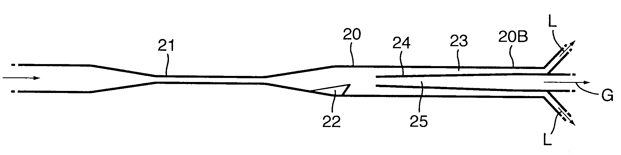
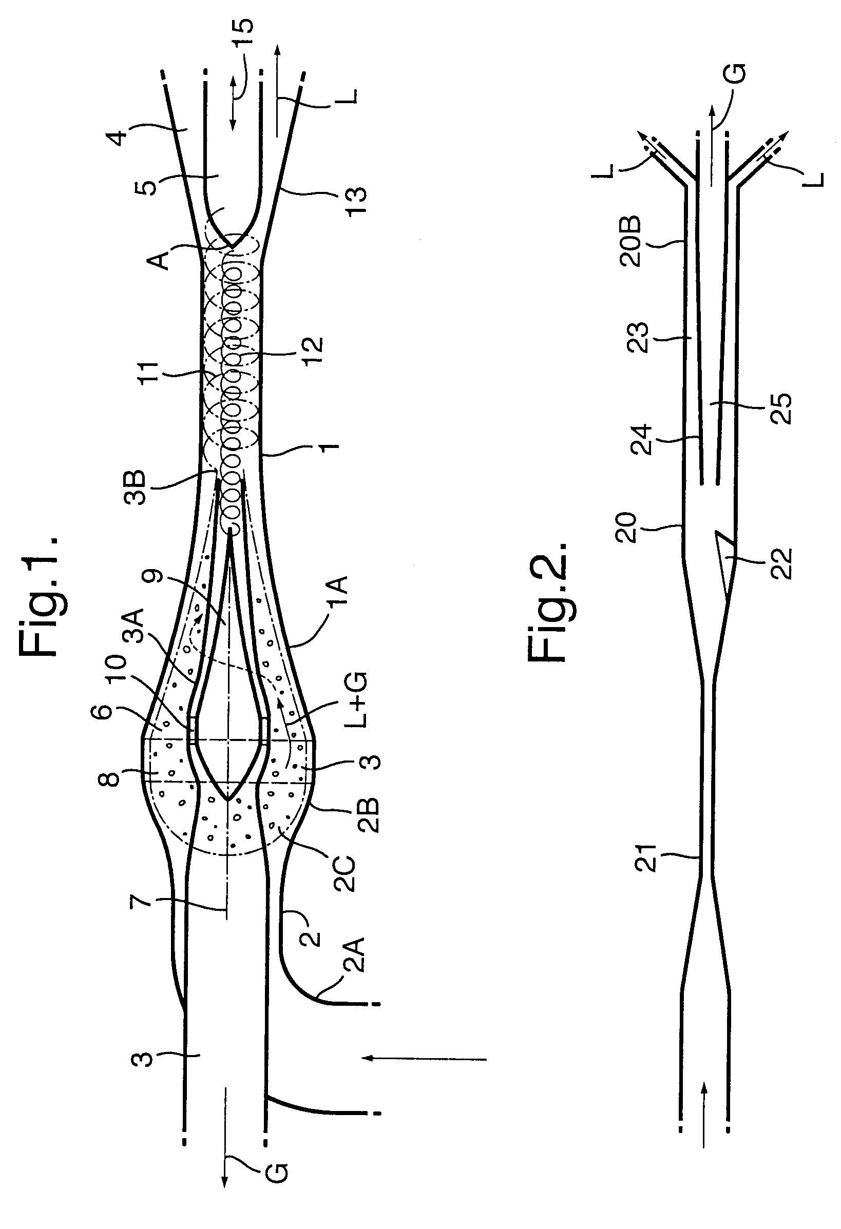
[0029]FIG. 1 depicts a cyclonic liquid degassing separator, which comprises a vortex tube 1, an untreated fluid inlet conduit 2, a gas outlet conduit 3 and a degassed liquid outlet conduit 4.

[0030]The vortex tube 1 has a trumpet-shaped proximal end 1A and a diverging distal end 1B.

[0031]The liquid outlet conduit 4 is formed by an annular space between the inner surface of the diverging distal end 1B of the vortex tube 1 and a bullet-shaped deflection body 5.

The trumpet-shaped proximal end 1A of the vortex tube 1 is connected to the diverging outer wall 2B of the fluid inlet conduit 2.

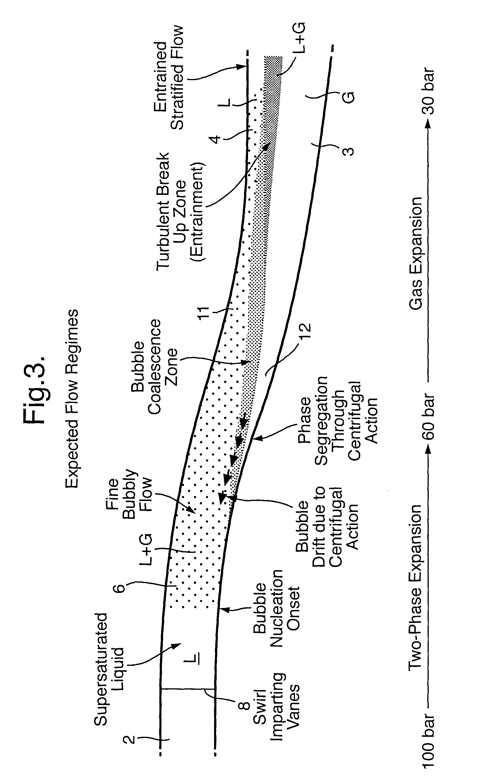
[0032]A series of swirl imparting vanes 8 is arranged in the diverging annular end-section 2C of the inlet conduit 2B, which vanes 8 induce the untreated fluid to swirl into an annular throat section 6 formed between the inner surface of the trumpet-shaped proximal end 1A of the vortex tube 1 and the outer surface of the wall 3A of the fluid outlet conduit 3.

[0033]The annular throat section 6 has a grad...


PUM

PropertyMeasurementUnit
pressureaaaaaaaaaa
pressureaaaaaaaaaa
static pressureaaaaaaaaaa

Abstract

A method and cyclonic separator are disclosed for degassing a fluid mixture comprising a carrier liquid and one or more gaseous and/or vaporizable components, wherein: —the fluid mixture is accelerated in a throat section (6) of a vortex tube (1) such that the static pressure of the fluid mixture is decreased and vaporizable components evaporate into a gaseous phase; —the accelerated fluid mixture is induced to swirl within the vortex tube such that the fluid mixture is separated by centrifugal forces into a degassed liquid fraction and a gas enriched fraction; —the degassed liquid fraction is induced to flow into a liquid outlet conduit (4) which is located at or near the outer circumference of the vortex tube (1); and—the gas enriched fraction is induced to flow into a gas outlet conduit (3) which is located at or near a central axis of the vortex tube (1).

Description

BACKGROUND OF THE INVENTION[0001]The invention relates to a cyclonic separator and method for degassing a fluid mixture.[0002]U.S. Pat. No. 6,402,799 discloses a cyclonic separator in which a gas-liquid mixture is injected via a tangential inlet into a horizontal vortex tube in which the gaseous and liquid fractions are at least partly separated and the liquid fraction forms a film alongside the inner wall of the vortex tube and is discharged via a radial outlet, whereas the gaseous fraction is concentrated near the central axis of the vortex tube and discharged via a central outlet.[0003]International patent applications WO9901194 and WO03029739 disclose cyclonic separators wherein a gas stream is accelerated in a vortex tube to a near sonic or supersonic velocity and thereby expanded and adiabatically cooled such that liquid or solid particles are formed which are discharged via an outlet at the outer circumference of the tube, whereas a dry gas fraction is discharged via a centra...

Claims


Application Information

Patent Timeline
Patent Type & Authority Applications(United States)
IPC IPC(8): B04C3/00B04C3/06B04C5/13B04C5/103B04C5/16B01D19/00
CPCB01D19/0057B04C3/00B04C3/06B04C5/103B04C5/13B04C5/16B04C5/181B04C2003/006
Inventor BETTING, MARCOCOLENBRANDER, GERHARDUS WILLEMCUROLE, MICHAEL ALVINKLAVER, THEODORUS CORNELISPUIK, ERIC JOHANNES
Owner SHELL OIL CO
Why Eureka
Try Eureka