Exhaust gas turbine and method of controlling the turbine

a technology of exhaust gas turbine and turbine wheel, which is applied in the direction of combination engines, motors, engine fuctions, etc., can solve the problems of affecting the function and cost of these known systems, affecting the efficiency of turbines which decrease corresponding to bleed flows, and affecting the positive charge changing process. , to achieve the effect of reducing the static pressure at the wheel outlet, reducing the static pressure, and reducing the effect of the exhaust gas counter pressure of the combustion engin

Inactive Publication Date: 2015-08-27
IHI CHARGING SYST INT
View PDF3 Cites 14 Cited by
  • Summary
  • Abstract
  • Description
  • Claims
  • Application Information

AI Technical Summary

Benefits of technology

[0014]Another advantage of the invention is the potential reduction of the exhaust gas counter pressure of the combustion engine. When the static pressure at the wheel outlet is reduced by means of the invention, there is also the possibility to decrease the static pressure at the wheel inlet so that a so-called exhaust gas counter pressure of the combustion engine is also reduced. Thus, it becomes possible to achieve an improved charge cycle of the combustion engine, which again may result in fuel reduction and thus in a reduction of pollutant emissions.
[0015]A particularly high pressure reduction at the wheel outlet may be achieved if the opening is formed in a boundary area between the wheel chamber and the outlet area. In particular, a leading edge of the opening, which faces the turbine wheel, is positioned at a distance from an impeller blade trailing edge of the turbine wheel. Ideally, the distance is determined depending on a turbine wheel diameter at the wheel outlet, wherein an optimum distance ranges from 0 to 0.15*turbine wheel diameter at the wheel outlet.
[0016]In another embodiment of the inventive exhaust gas guide section, the flow cross-section of the opening is the smallest cross-section of the bypass duct. When the smallest flow cross-section of the bypass duct is located at the opening, a special ejector effect may be achieved. This means, as soon as the fluid from the bypass duct flows into the outlet area via the opening, a reduction of the static pressure at the wheel outlet may be achieved.
[0017]A further increase in pressure reduction at the wheel outlet may be achieved if the bypass duct is inclined at an angle relative to an axis of rotation of the turbine wheel. The bypass duct is to be formed in such a manner that the bypass duct is inclined toward the outlet area. That a duct axis of the bypass duct in the area of the opening should extend at an acute angle relative to the axis of rotation of the turbine wheel. Ideally, the angle of inclination ranges from 20° to 40°. Thereby an optimum ejector effect and thus a considerable pressure reduction at the wheel outlet may be achieved.
[0018]In order to obtain a large-area effective range of the ejector effect, the flow cross-section of the opening is advantageously formed annular in the exhaust gas guide section. This means that the flow cross-section is formed over the entire wheel circumference of the turbine wheel at the wheel outlet. An annular flow cross-section of the opening which is formed concentric to the axis of rotation of the turbine wheel is particularly advantageous.
[0019]In another advantageous embodiment of the inventive exhaust gas guide section, the outlet duct is formed diffusor-type or as a diffusor, respectively. This diffusor-type configuration enhances the ejector effect, so that an additional pressure reduction at the wheel outlet may be achieved.

Problems solved by technology

The reason is that Diesel engine combustion may be considerably influenced by charging in respect to fuel consumption, while this is not the case with Otto engine combustion because of the limited range of the combustion air / ratio with which combustion can be obtained.
The turbine efficiency which decreases corresponding to the bleed flows is generally disadvantageous, in particular in a waste gate turbine, which primarily at high bleed flows—with smaller combustion engines with.
Otto engine combustion bleed flows up to 50% are not uncommon—negatively influences a positive charge changing process.
In view of the considerably higher exhaust gas temperatures which occur in the Otto engine combustion and the inherent challenges concerning function and costs these known systems, however, have serious limitations.

Method used


Image

  • Exhaust gas turbine and method of controlling the turbine
  • Exhaust gas turbine and method of controlling the turbine
  • Exhaust gas turbine and method of controlling the turbine

Examples


Embodiment Construction

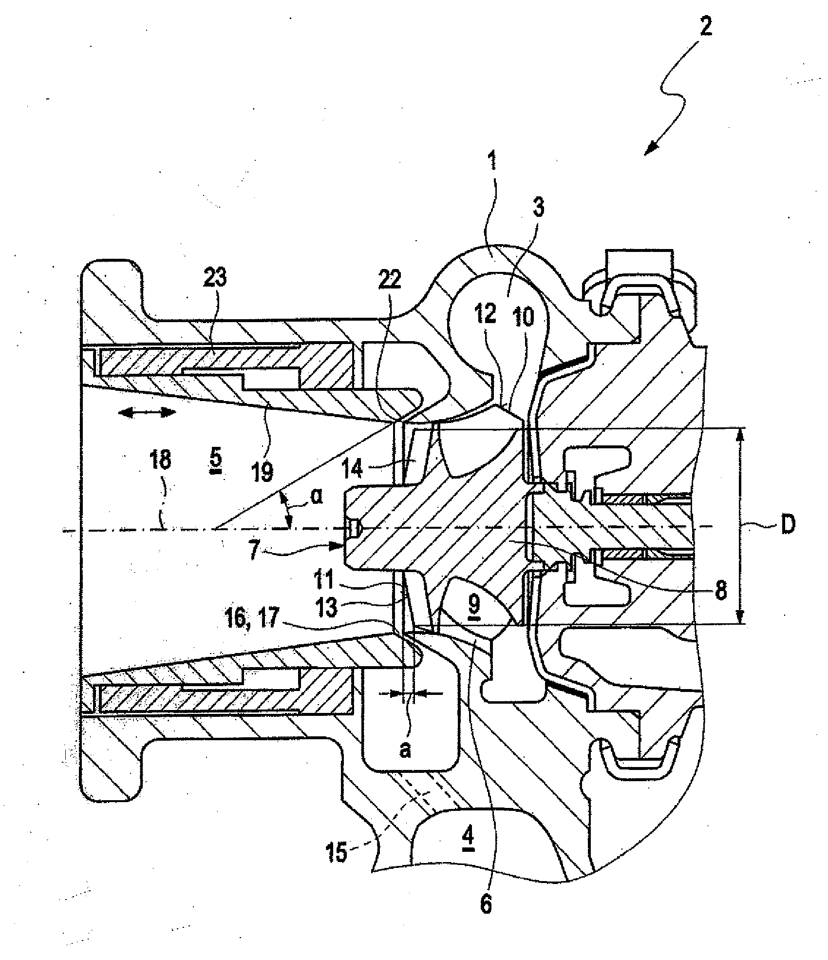
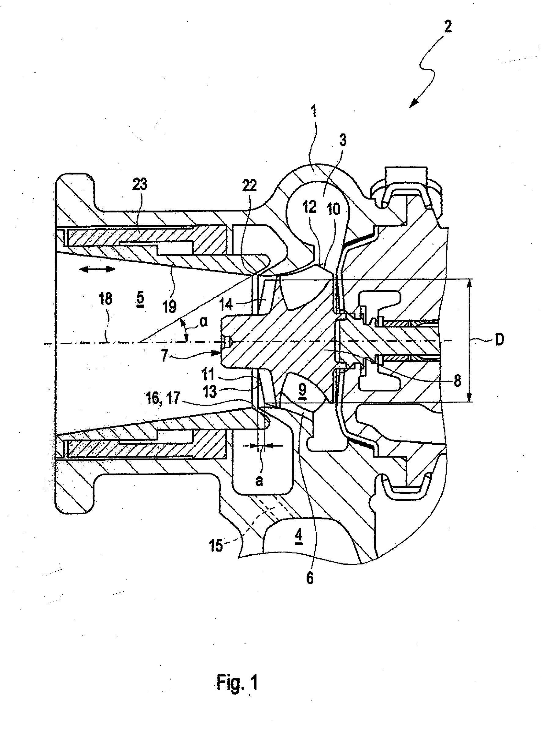
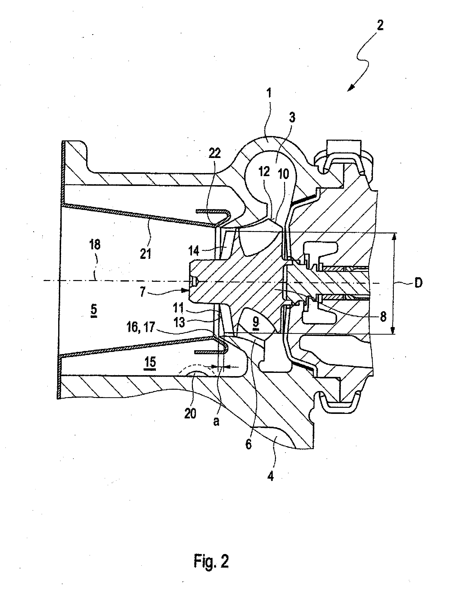
[0028]An inventive flow-through exhaust gas guide section 1 according to FIG. 1 of a turbine 2, in particular a turbine of an exhaust gas turbocharger, comprises a flow duct 3 for conducting the exhaust gas, in particular the exhaust gas of a combustion engine to a turbine wheel 7. The flow duct 3 comprises an inlet portion 4 through which the fluid flow enters the exhaust gas guide section 1 and an outlet portion 5 through which the fluid is discharged from the exhaust gas guide section 1. Between the inlet portion 4 and the outlet portion 5 a wheel chamber 6 is arranged in the exhaust gas guide section 1. The turbine wheel 7 is rotatably accommodated in the wheel chamber 6.

[0029]The turbine wheel 7 comprising a hub 8 and a plurality of impeller vanes 9 fixed at the hub has a wheel inlet 10 and a wheel outlet 11. The wheel inlet 10 is formed at an outermost impeller vane leading edge 12 of an impeller vane 9 and the wheel, outlet 11 is formed at an outermost impeller vane trailing ...


PUM


Abstract

In an exhaust gas turbine with a guide section for the exhaust gas turbine comprising a flow-through duct for conducting exhaust gas through the exhaust gas guide section, wherein the flow-through duct includes a wheel chamber in which a turbine wheel is rotatably supported and wherein, downstream of the wheel chamber, the flow-through duct has an outlet portion and upstream of the wheel chamber, the flow-through duct has an inlet portion with a bypass duct being formed in the exhaust gas guide section for by-passing the wheel chamber, the by-pass duct forms an annular opening adjacent the turbine wheel for directing by-pass exhaust gas into the exhaust gas outlet portion in an annular flow pattern along the outlet portion duct wall.

Description

[0001]This is a Continuation-in-Part application of pending international patent application PCT / EP2013 / 003725 filed 2013 Dec. 10 and claiming the priority of German patent application 10 2012 112 396.9 filed 2012 Dec. 17.BACKGROUND OF THE INVENTION[0002]The invention relates to an exhaust gas turbine with a turbine wheel arranged in a housing which includes a by-pass duct structure to permit the exhaust gas to by-pass the turbine wheel.[0003]In the past, charging of internal combustion engines by means of an exhaust gas turbocharger was mainly used in connection with to Diesel engines. Otto engines are only rarely provided with a charging unit. The reason is that Diesel engine combustion may be considerably influenced by charging in respect to fuel consumption, while this is not the case with Otto engine combustion because of the limited range of the combustion air / ratio with which combustion can be obtained.[0004]However, the present objective is to reduce a piston displacement of...

Claims


Application Information

Patent Timeline
Patent Type & Authority Applications(United States)
IPC IPC(8): F01D17/10F02C6/12F02B37/18
CPCF01D17/105F02B37/183F05D2260/60F05D2220/40F02C6/12
Inventor EHRHARD, JANFILSINGER, DIETMARGUTHOERLE, MANFREDFLEDERSBACHER, PETER
Owner IHI CHARGING SYST INT
Why Eureka
Try Eureka