Method for manufacturing multi-pitch flashing

a manufacturing method and flashing technology, applied in the field of flashing, can solve problems such as not being able to be automatically mass produced

Inactive Publication Date: 2008-11-27
METALICO INC
View PDF7 Cites 14 Cited by
  • Summary
  • Abstract
  • Description
  • Claims
  • Application Information

AI Technical Summary

Problems solved by technology

This method suffers from the problem of the creation of a hole if the speed of rotation is too slow or the torch is held too close, if the operator tries to avoid holes by permitting the table to rotate too fast or keeping the torch too far from the juncture, fusion between the supplementary metal and the lead sheet and cylindrical sleeve being joined will not occur.
This method suffers from the awkward positions of the table and the workpieces, which are angled at 45 degree with respect to the horizontal, and therefore do not lend themselves to automatic mass production.

Method used


Image

  • Method for manufacturing multi-pitch flashing
  • Method for manufacturing multi-pitch flashing
  • Method for manufacturing multi-pitch flashing

Examples


Embodiment Construction

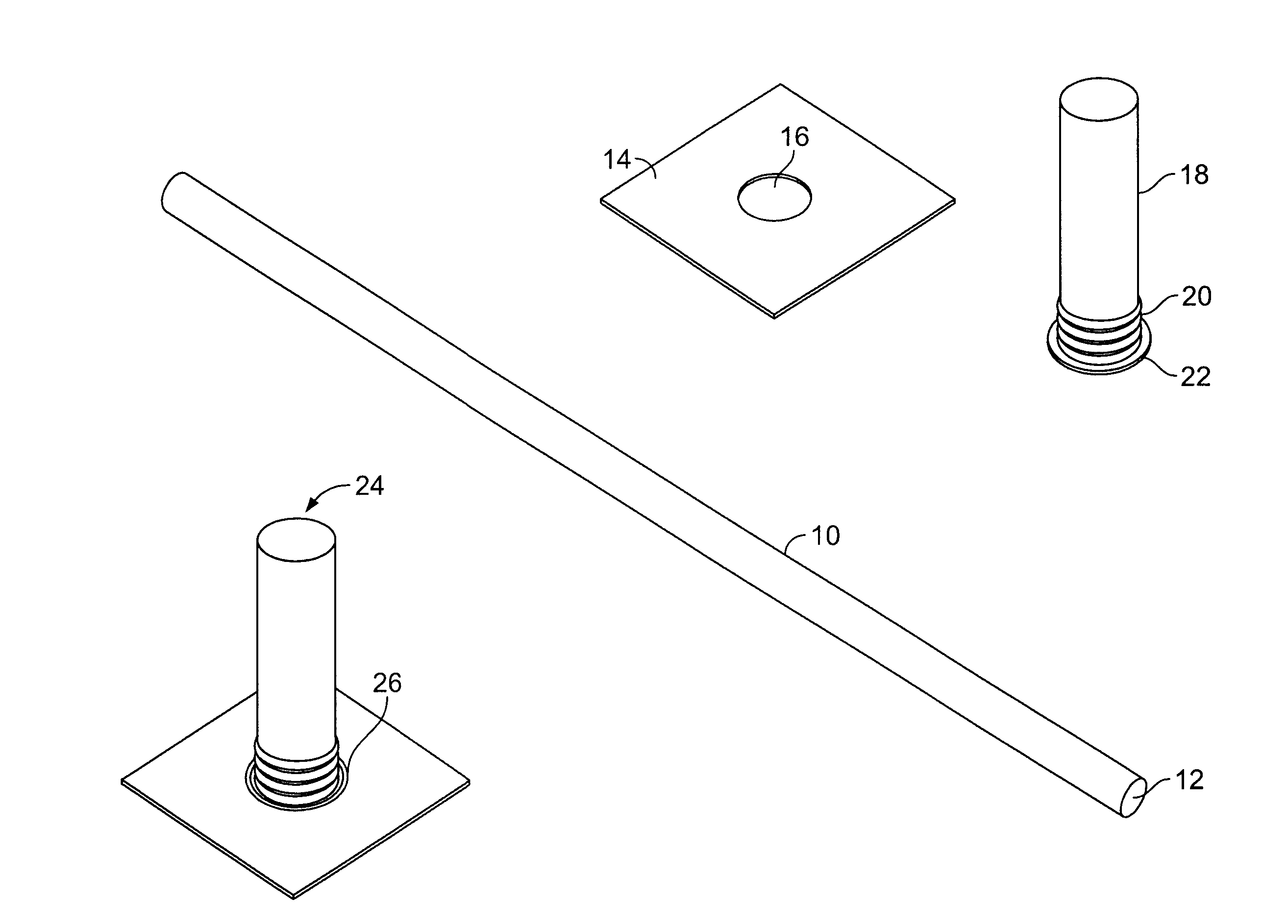
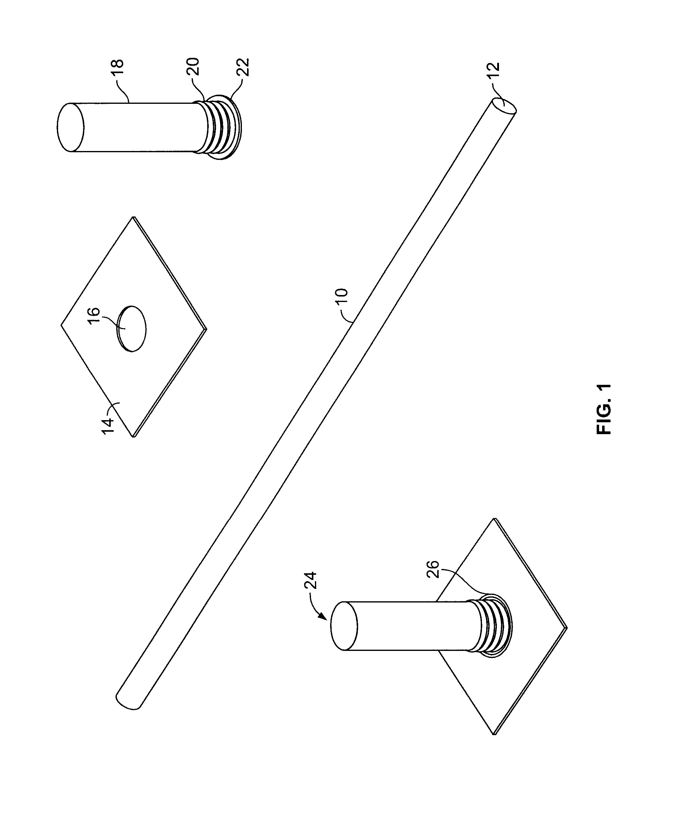
[0022]Referring now to FIG. 1, there is shown a full length lead pipe 10 (labeled Part #1) having an inner opening 12, and a flat lead sheet 14 (labeled Part #3) having a hole 16 at its center. The lead pipe 10 is to be shaped and then welded (preferentially TIG welded) to the sheet 14 at the position of the hole 16 such that the inner opening 12 of the pipe 10 lines up with the hole 16 of the lead sheet 14. While the present invention is discussed in the context of a cylindrically-shaped lead pipe, a person skilled in the art would appreciate that the present invention is applicable to hollow pipe flashing of any size, shape, and cross section. The pipe 10 and the sheet 14 are also not limited to lead, but can be made of any suitable material capable of being welded. According to an embodiment of the present invention, a finished pipe 18 (Labeled Part #2) is fashioned from the lead pipe 10 using a Multi-Pitch Flashing Machine to be described below. The lead pipe 10 is straightened,...


PUM

PropertyMeasurementUnit
angleaaaaaaaaaa
angleaaaaaaaaaa
pressureaaaaaaaaaa

Abstract

A method for manufacturing lead flashing for a roof pipe is disclosed. A lead pipe is straightened and then pushed into a frictionally engaged knurled clamp. Pressure is applied between a knurled head of a knurler and the inner surface of the lead pipe and the knurler is rotating about the inner surface of the lead pipe. This causes the lead pipe to conform to the knurles of the knurled clamp and the knurled head, while causing a portion of the lead pipe extending beyond the knurled clamp to be contoured and swaged into a flange. At a multi-position horizontally positioned rotatable table, the flange of the knurled lead pipe is flattened to overlap a flat lead sheet having a hole cut from its center. The knurled lead pipe flange and flat lead sheet are arc-welded together with a TIG weld gun. After welding, the finished lead pipe flashing is moved onto a packaging feed conveyor via a vacuum lifter.

Description

FIELD OF THE INVENTION[0001]The present invention relates generally to flashing, and more particularly to a method for manufacturing the flashing used for roof pipes.BACKGROUND OF THE INVENTION[0002]In the construction industry, a wide variety of roofing applications in the commercial, industrial, and residential construction industries have led to the need for flashing devices and materials for protecting roofing structures from the elements, such as water, ice, and dust. Flashing is commonly used at locations where a pipe passes through the roof. The flashing prevents rain water from running down the outside of the pipe and leaking into the building. Flashing for a pipe typically comes in the form of cylindrical sleeve made of lead and having an inner diameter that is slightly greater than the pipe being protected. The cylindrical sleeve is attached to a flat sheet, also made of lead, with a circular hole punched from it, which is joined to the cylindrical sleeve.[0003]The junctio...

Claims


Application Information

Patent Timeline
Patent Type & Authority Applications(United States)
IPC IPC(8): B23K31/02B23K9/167
CPCB23K9/0288B23K9/167B23K33/00E04D13/1476
Inventor FLEMING, DONALD P.MCLEAN, GEORGE D.
Owner METALICO INC
Why Eureka
Try Eureka