Heating stage for a micro-sample

a micro-sample and heating stage technology, applied in the direction of material analysis using wave/particle radiation, instruments, nuclear engineering, etc., can solve the problems of large interference with the observation within the electron microscope, large heat loss, and difficult observation, and achieve accurate observation of the micro-sample. , the effect of efficient heating

Inactive Publication Date: 2008-11-27
HITACHI HIGH-TECH CORP
View PDF2 Cites 25 Cited by
  • Summary
  • Abstract
  • Description
  • Claims
  • Application Information

AI Technical Summary

Benefits of technology

[0015]The present invention can achieve the heating stage for the micro-sample and the heating holder for the micro-sample, capable of efficient heating and accurate observation of the micro-sample.

Problems solved by technology

However, the conventional art encounters the actual situation where the amount of heat generated by the heater is almost entirely taken by the stage for mounting the heater, the mesh actually fixing the sample, or the like, and hence the amount of heat is not conducted throughout the sample to be actually heated.
For this reason, even a further increase in the heater temperature does not effect the narrowing of a temperature differential between the heater temperature and the sample temperature, which in turn can interfere greatly with observation within the electron microscope due to the fact that an increase in the sample temperature requires an increase in the heater temperature.
In other words, a rise in the heater temperature can lead to gases originating from other members, thus causing the drifting of an image obtained by the electron microscope, and hence rendering the observation difficult.

Method used


Image

  • Heating stage for a micro-sample
  • Heating stage for a micro-sample
  • Heating stage for a micro-sample

Examples


first embodiment

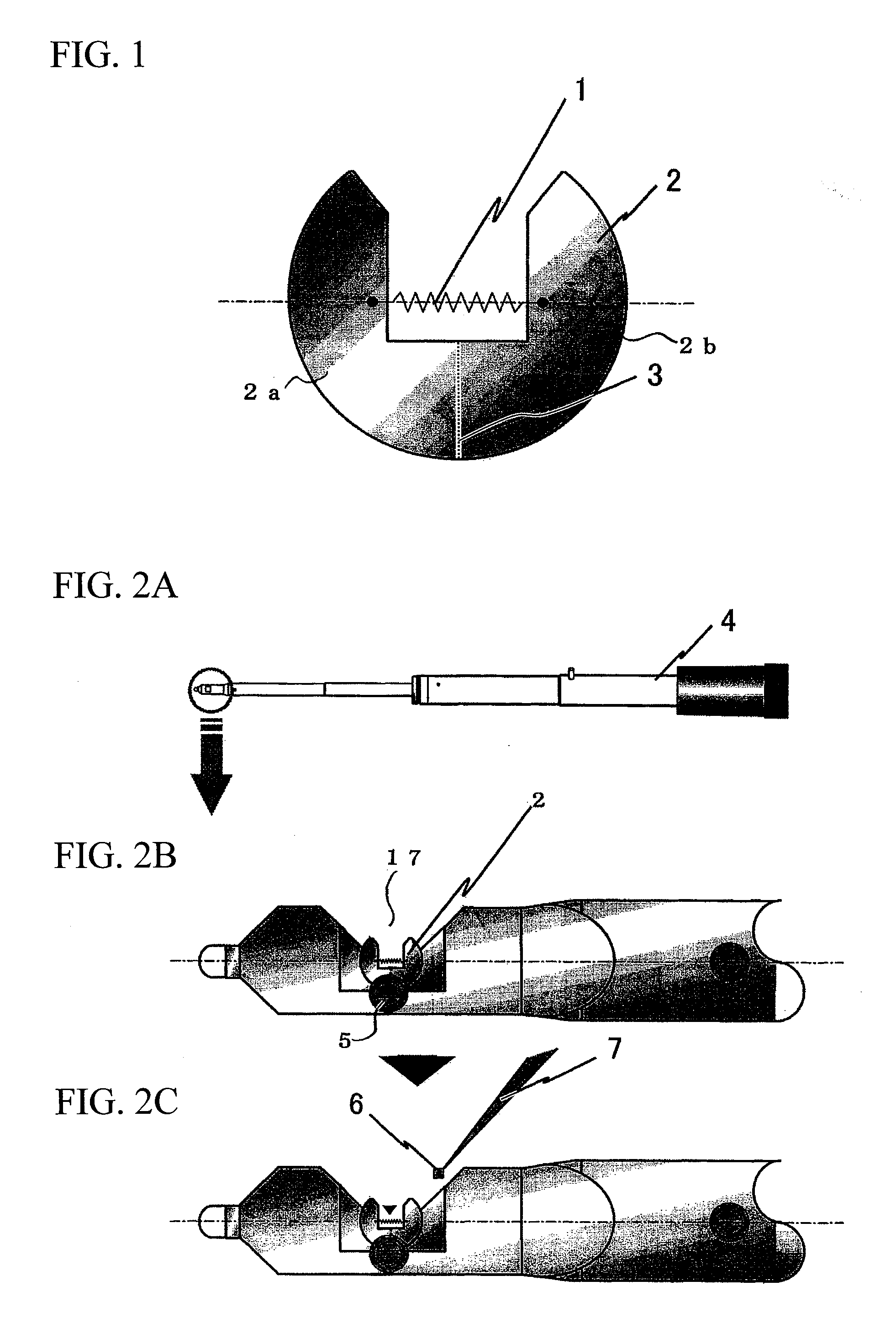
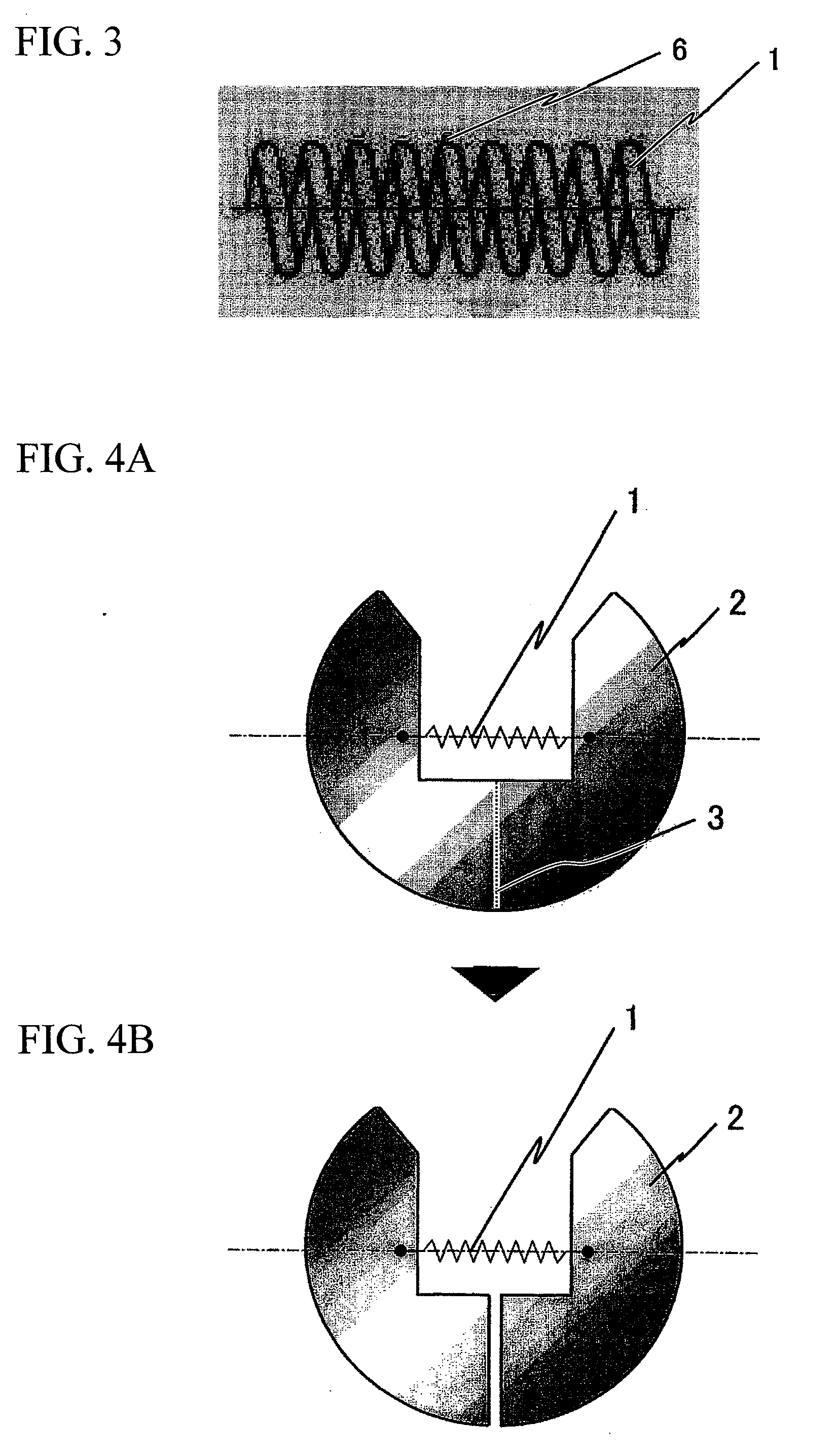
[0030]FIG. 1 is a top view of a principal part of a heating stage for a micro-sample according to a first embodiment of the present invention. In FIG. 1, a micro-sample mount 1 is a heating portion in spiral form (or coil form), made of a very hard and high-melting point material such as tungsten or molybdenum. The micro-sample mount 1 is fixed at both ends to a base 2 for the heating stage for the micro-sample, made of a material such as molybdenum stainless steel.

[0031]Specifically, the base 2 can be divided into two semicircular supporting members 2a and 2b along a base cut line 3, and the micro-sample mount 1 is fixed at one end to the first supporting member 2a and is fixed at the other end to the second supporting member 2b. The supporting members 2a and 2b of the base 2, although integral with each other in their original positions, are configured so that they can be separated from each other along the base cut line (e.g., perforations) 3.

[0032]The base 2 for the heating stag...

second embodiment

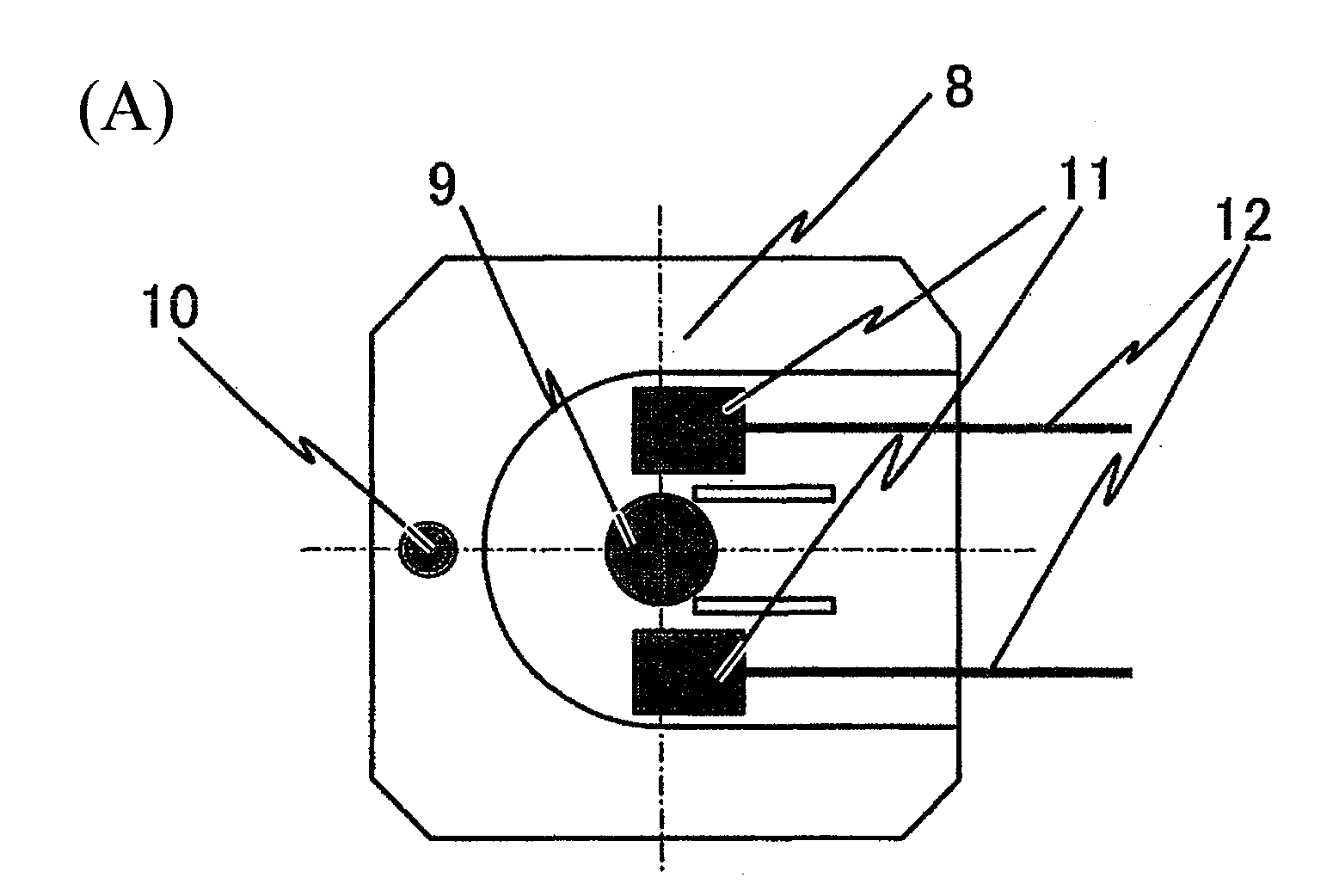
[0043]FIG. 7 is a view of the general configuration of a second embodiment of the present invention. The above-mentioned first embodiment has a configuration in which the stage 8 having the base 2 for the heating stage, mounting the micro-sample 6, is supported by the holder 15; however, the second embodiment has a configuration in which a micro-sample mount 1 is formed in an electron beam passage opening 17 formed at the tip of a holder 16 for common use in the instrument for observation based on the focused ion beam process and the transmission electron microscope or the ultra thin film evaluation instrument.

[0044]In FIG. 7, the micro-sample mount 1 for mounting a micro-sample 6 is a heating unit in spiral form made of a high-melting point material such as tungsten or molybdenum. The heating unit is fixed at both ends to the tip portion of the holder 16 made of a material such as stainless steel by first and second supporting members 18a and 18b.

[0045]After that, the sample subje...


PUM


Abstract

The present invention achieves a heating stage for a micro-sample, capable of efficient heating and accurate observation of the micro-sample. A micro-sample mount is a heating portion in coil form and is fixed at both ends to a base for the heating stage for the micro-sample. The base can be divided into two members at a base cut line, and the mount is fixed at one end to the first member and is fixed at the other end to the second member. A sample subjected to micro-sampling is mounted on the mount. The base is removed from the tip of a holder, and is mounted on a stage for the sample stage. A current is fed to the micro-sample mount through the members to thereby apply heat to a micro-sample for observation.

Description

BACKGROUND OF THE INVENTION[0001]1. Field of the Invention[0002]The present invention relates to a heating stage for a micro-sample, which is used for efficient heating and observation of a sample as subjected to a micro-sampling process by an instrument for observation based on a focused ion beam process.[0003]2. Description of the Related Art[0004]The heating and observation of a powder sample, when performed for the heating and observation of a given micro-sample, involves fixing the powder sample directly on a coil heater for heating, thereby carrying out the heating and observation.[0005]This is an effective means for the heating and observation of the powder sample because the heater also serves as a part for fixing the powder sample and thus the sample is directly heated and hence affected little by removal of heat in an atmosphere of vacuum in a sample chamber of an electron microscope (See Japanese Patent Application Publication No. Hei 6-44936).[0006]On the other hand, the...

Claims


Application Information

Patent Timeline
Patent Type & Authority Applications(United States)
IPC IPC(8): H01J37/20
CPCH01J37/20H01J37/26H01J2237/2001H01J2237/31745
Inventor NAGAKUBO, YASUHIRATANIGAKI, TOSHIAKIITOU, KATSUJIKANEMURA, TAKASHIASAKAWA, TAKAYUKI
Owner HITACHI HIGH-TECH CORP
Why Eureka
Try Eureka