Asymetrical K-Ring

a technology of k-rings and rings, applied in the field of sealing rings, can solve the problems of increasing ware, increasing ware, and causing unwanted friction between the piston and the cylinder wall, and achieving the effect of increasing the radial pressur

Inactive Publication Date: 2008-11-27
NORGREN INC (US)
View PDF24 Cites 2 Cited by
  • Summary
  • Abstract
  • Description
  • Claims
  • Application Information

AI Technical Summary

Benefits of technology

[0028]a means for increasing the radial pressure exerted by the K

Problems solved by technology

Even with force 318 counteracting force 314, the sealing force may still be too large and create unwanted friction between the piston and the cylinder wall.
Another problem with the current K-rings is the distribution of the sealing force across the dyn

Method used


Image

  • Asymetrical K-Ring
  • Asymetrical K-Ring
  • Asymetrical K-Ring

Examples


Embodiment Construction

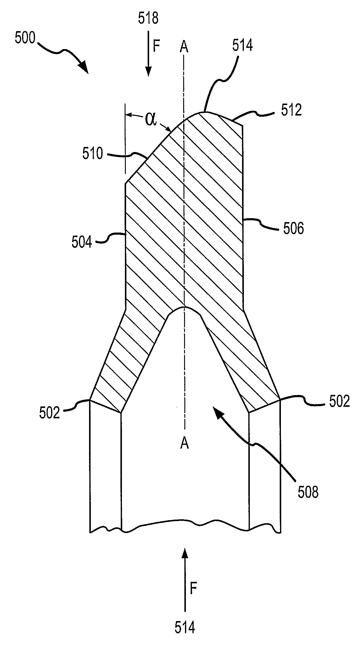
[0034]FIGS. 5 and the following description depict specific examples to teach those skilled in the art how to make and use the best mode of the invention. For the purpose of teaching inventive principles, some conventional aspects have been simplified or omitted. Those skilled in the art will appreciate variations from these examples that fall within the scope of the invention. Those skilled in the art will appreciate that the features described below can be combined in various ways to form multiple variations of the invention. As a result, the invention is not limited to the specific examples described below, but only by the claims and their equivalents.

[0035]FIG. 5 is a cross sectional view of asymmetric K-ring 500 in an example embodiment of the invention. K-ring 500 has two sealing rims 502, a left face 504, a right face 506, a cavity 508 formed in the inner diameter of the K-ring, a left bevel 510, a right bevel 512, and a dynamic sealing surface 514. Bevel 510 forms an angle o...


PUM

PropertyMeasurementUnit
Angleaaaaaaaaaa
Radiusaaaaaaaaaa
Forceaaaaaaaaaa

Abstract

A system and method for an asymmetric K-ring is disclosed. The system and method is for forming a K-ring with the dynamic sealing surface (514) closer to one edge or face (506) of the k-ring than the other edge or face (504) . The asymmetrically placed dynamic sealing surface creates a larger bevel (510) on one side of the K-ring thereby reducing the sealing force produced by the K-ring when pressure is applied to the side of the K-ring with the larger bevel

Description

BACKGROUND OF THE INVENTION[0001]1. Field of the Invention[0002]The invention is related to the field of sealing rings, and in particular, to an asymmetric K-ring.[0003]2. Description of the Prior Art[0004]Sealing rings come in many varieties. One of the best known sealing rings is the O-ring. Another type of sealing ring is the K-ring. The K-ring was originally developed by the Knorr-Bremsen Company (also known as the Knorr-Breaks Company). The original K-ring is used in the drives for pneumatic brakes. K-rings have two variations, the first type moves with the piston (see FIG. 1a) and the second type is captured by the cylinder (see FIG. 1b). FIG. 2 is a cross sectional view of K-ring 200 of the first type. K-rings typically have 2 sealing rims 202, a left face 204, a right face 206, a cavity 208 formed in the inner diameter of the K-ring, a left bevel 210, a right bevel 212, and a dynamic sealing surface 214. The left and right bevels 210 and 212 make and angle α with respect to ...

Claims


Application Information

Patent Timeline
IPC IPC(8): F16J15/32F16J15/16B23P25/00
CPCF16J15/164Y10T29/4998F16J15/3204
Inventor RUST, MARTIN GOTTLOB
Owner NORGREN INC (US)
Why Eureka
Try Eureka