Vehicle expansion tank sealing, sealing assembly, vehicle expansion tank and vehicle with expansion tank

A technology of sealing components and seals, which is applied in the field of vehicle expansion tank sealing, can solve the problems of cooling system efficiency reduction, etc., and achieve the effects of reducing expansion tank leakage and effective vehicle cooling system

Active Publication Date: 2019-06-21
SCANIA CV AB
View PDF8 Cites 0 Cited by
  • Summary
  • Abstract
  • Description
  • Claims
  • Application Information

AI Technical Summary

Problems solved by technology

As a result, the efficiency of

Method used


Image

  • Vehicle expansion tank sealing, sealing assembly, vehicle expansion tank and vehicle with expansion tank
  • Vehicle expansion tank sealing, sealing assembly, vehicle expansion tank and vehicle with expansion tank
  • Vehicle expansion tank sealing, sealing assembly, vehicle expansion tank and vehicle with expansion tank

Examples


Embodiment Construction

[0034] Embodiments herein will now be described more fully with reference to the accompanying drawings, in which some embodiments are shown. Like numbers refer to like elements throughout. Well-known functions or constructions are not necessarily described in detail for brevity and / or clarity.

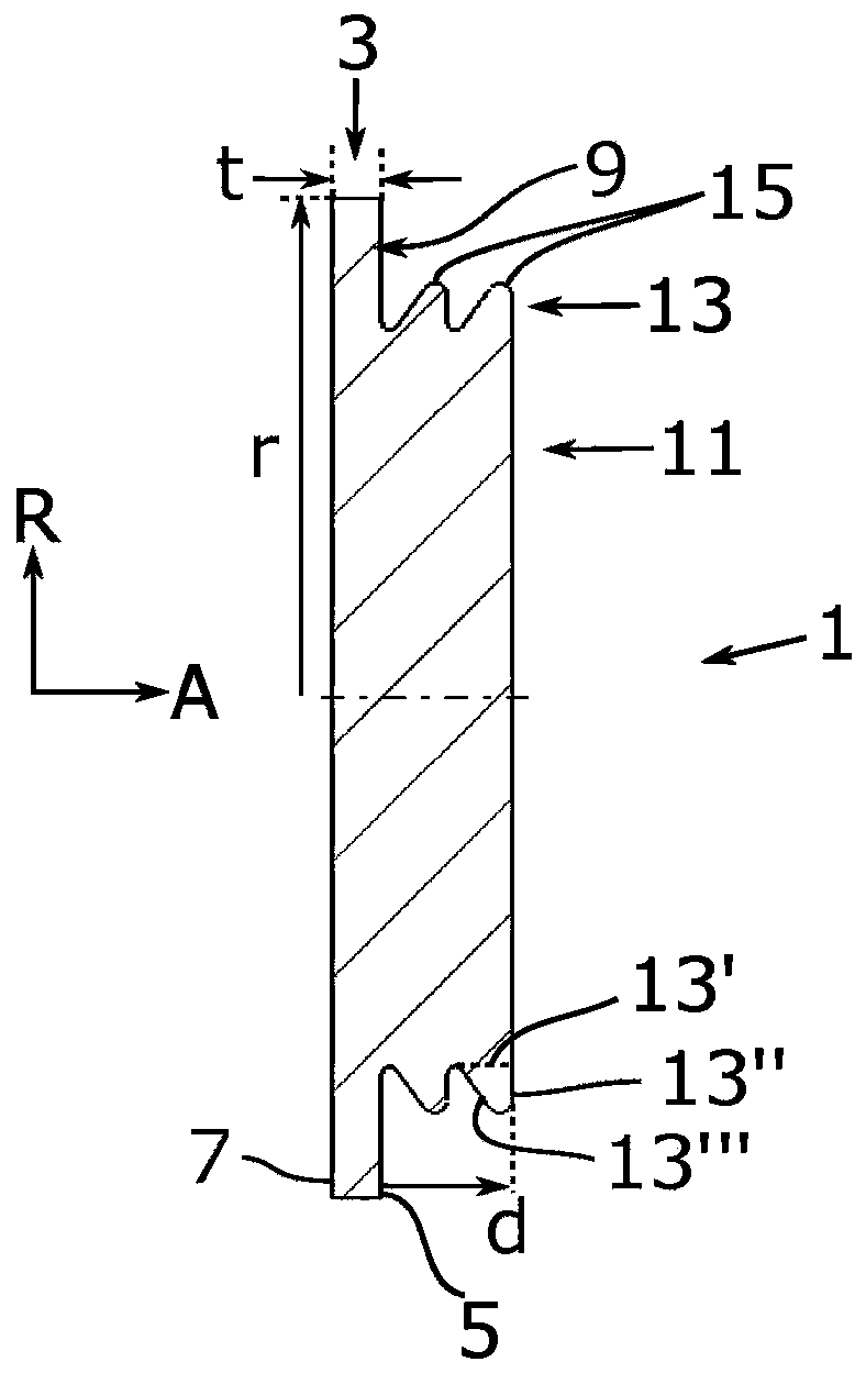
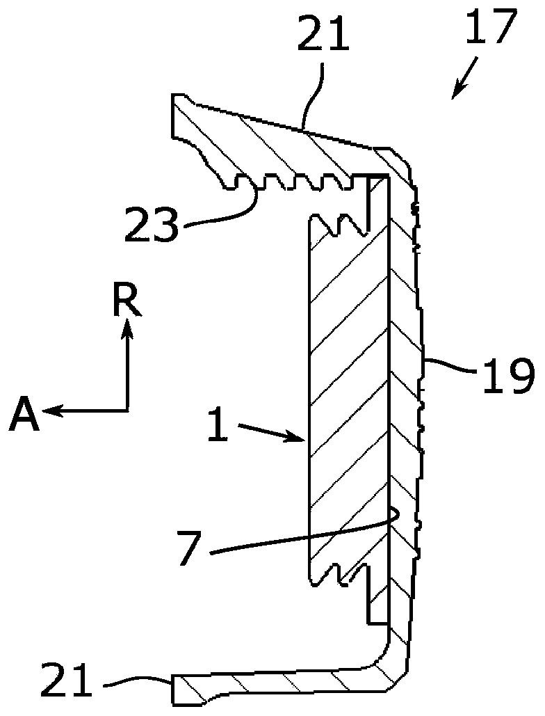
[0035] figure 1 A vehicle expansion tank seal 1 is shown. The can seal 1 comprises a generally disc-shaped portion 3 having a thickness t in the axial direction A between a first side 5 and a second side 7 . The disc-shaped portion has a radius r in the radial direction R. Directions A and R are given by figure 1 indicated by the arrow in . Select the radius r after the seal assembly / cover assembly to which the seal belongs. Such as figure 2 As shown, the radius can be selected to cover a substantial portion of the inner surface of the flat cover. In the figures herein, the disk-shaped portion is shown as being substantially circular, but it could alternatively be eg hexagonal...


PUM


Abstract

A vehicle expansion tank sealing (1), a sealing assembly (17), a vehicle expansion tank (31) and a vehicle (41) are provided. The sealing (1) comprises a substantially disc-shaped portion (3) with a thickness (t) between a first side (5) and a second side (7) in an axial direction (A), a radius (r) in a radial direction (R) and an axial sealing surface (9) arranged at a peripheral part (10) of thefirst side (5). The sealing (1) further comprises a centre portion (11) which protrudes a predetermined distance (d) from the disc-shaped portion (3) on the first side (5) in the axial direction (A)radially inwards of the axial sealing surface (9), and in that the centre portion (11) comprises at least one peripheral flange (13) which extends in the radial direction (R), the at least one peripheral flange (13) comprising a radial sealing surface (15).

Description

technical field [0001] Embodiments herein relate to vehicle expansion tank sealing. Embodiments herein also relate to a vehicle expansion tank seal assembly, a vehicle expansion tank, and a vehicle including the vehicle expansion tank. Background technique [0002] Vehicles such as trucks may include a coolant system for cooling, for example, an internal combustion engine and / or its passenger compartment. Such systems typically include a radiator with a cooling fan, a water pump, a thermostat, hoses and a coolant expansion tank. Cooling fluid is circulated through the radiator via the pump and hoses of the coolant system, and the temperature of the fluid is lowered by the air flow through the radiator. The heat sink may also include a cooling fan for increasing air flow through the heat sink. The cooled fluid can then cool the internal combustion engine. [0003] The temperature of the fluid or coolant may vary, for example, depending on ambient temperature and waste hea...

Claims


Application Information

Patent Timeline
IPC IPC(8): F01P11/02F24D3/10
CPCF01P11/0214F01P2011/0228F01P11/029F01P11/0209Y10S277/944
Inventor M·穆斯托宁Z·卡多斯J·胡尔特
Owner SCANIA CV AB
Why Eureka
Try Eureka