Electrical hand-held power tool with cooling of electronics

a technology of electronic devices and power tools, which is applied in the direction of manufacturing tools, portable power tools, mechanical energy handling, etc., can solve the problems of limiting the arrangement of auxiliary flow paths and electronic devices, and achieve the effect of preventing unsatisfactory flow resistan

Inactive Publication Date: 2008-11-27
HILTI AG
View PDF9 Cites 36 Cited by
  • Summary
  • Abstract
  • Description
  • Claims
  • Application Information

AI Technical Summary

Benefits of technology

[0014]Advantageously, the motor switch has a switch cooling plate that at least partially extends into the side opening. The switch cooling sheet insures also an adequate cooling of the regions of the switch spaced by a large distance from the auxiliary flow path.
[0015]It is particularly advantageous when the switch cooling plate limits the auxiliary flow path flush with the air conducting elements. Thereby, on one hand, an undesirable flow resistance is prevented and, on the other hand, the switch cooling plate can be used simultaneously as an air conducting element.

Problems solved by technology

The drawback of the known device consists in that because of the pressurized nature of the air guiding arrangement, at least its inlet opening must be located adjacent to the fan wheel in the radial direction of the fan wheel in order to be able to direct the air flow into the flow path.
However, this significantly limits the possibility of arrangement of the auxiliary flow path and also of the electronic device.

Method used


Image

  • Electrical hand-held power tool with cooling of electronics
  • Electrical hand-held power tool with cooling of electronics
  • Electrical hand-held power tool with cooling of electronics

Examples


Embodiment Construction

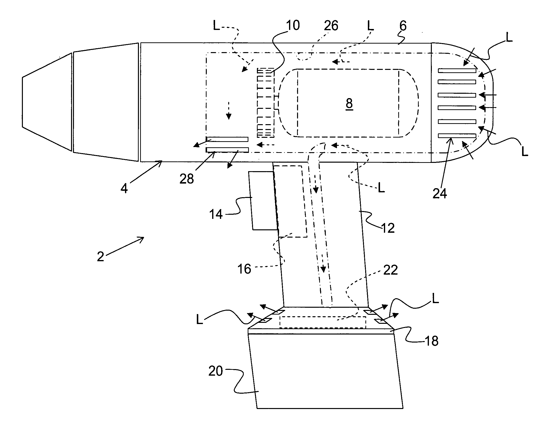
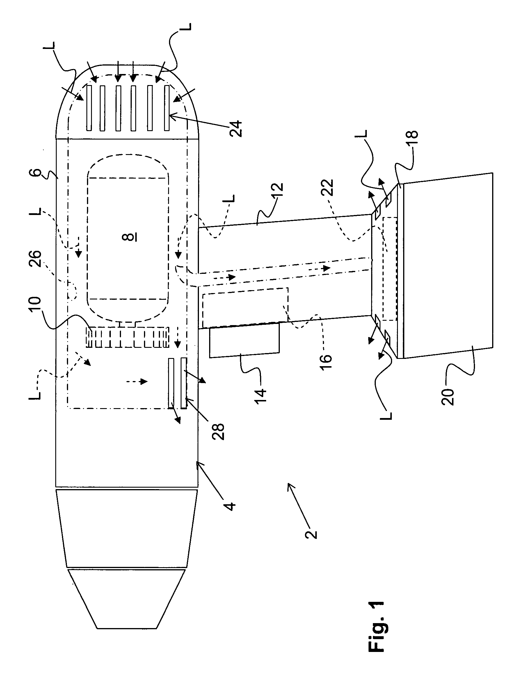
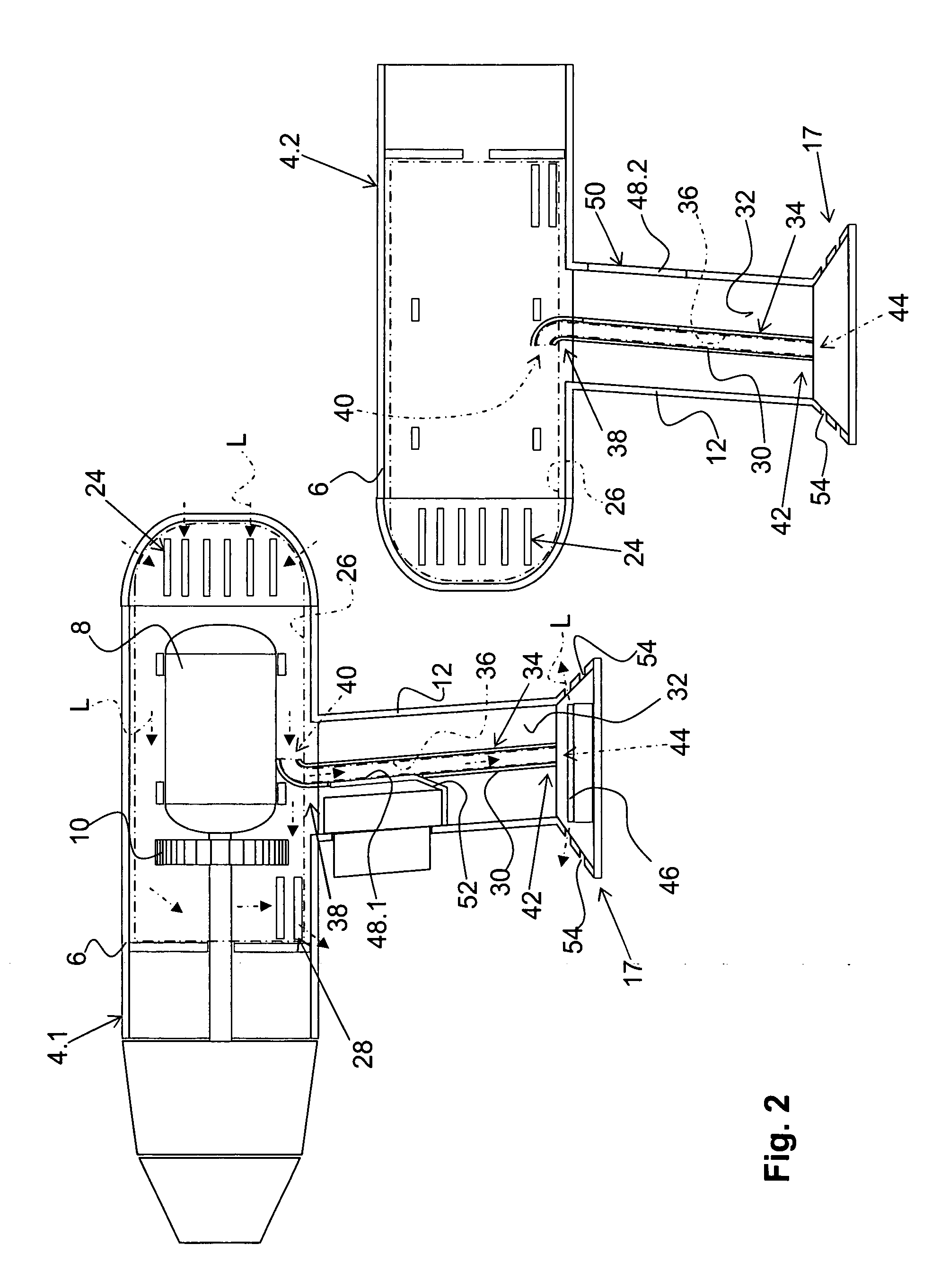
[0020]A electrical hand-held power tool 2, which is shown in FIG. 1 and is formed, e.g., as a screwdriving tool with the use of accumulator(s) as a power source, includes a housing 4 having a drive housing part 6 in which a drive motor 8 with a ventilation device 10 are received, and a handle housing part 12 on which a switch rawl 14 for actuation a motor switch 16, which is located in the handle housing part 12, is provided. Further, an end section 17 of the handle housing part 12 remote from the drive housing part 6, is provided with an interface 18 for mounting an accumulator package 20. An electronic device 22, which controls the drive motor 8 in a manner not shown in the drawings, is arranged on the interface 18. Alternatively, the hand-held power tool 2 can be formed as a network-powered power tool, with the electronic device 22 being arranged, in this case, e.g., on a distribution plate connected with the feeding cable.

[0021]As can be seen in FIGS. 1-2, during the operation o...


PUM


Abstract

An electrical hand-held power tool includes a drive motor, a ventilation device (10) for generating an air flow (L) along a main flow path (26) for cooling the drive motor (8), and an electronic device (22) for controlling operation of the drive motor (8) all of which are located in the housing (4), and a plurality of air conducting elements (30) that project from an inner wall (32) of the housing for limiting an auxiliary flow path (36) through which at least a portion of the air flow (L) is forwarded to the electronic device (22), with the air conducting elements (30) forming an auxiliary path inlet (40) of the auxiliary flow path (36) and which projects between a main path inlet (24) of the housing (4) and the ventilation device (10) into the main flow path (26), so that the auxiliary path inlet (40) is walled off from the ventilation device (10).

Description

BACKGROUND OF THE INVENTION[0001]1. Field of the Invention[0002]The present invention relates to an electrical hand-held power tool including a drive motor located in the power tool housing, and a ventilation device also located in the housing. The ventilation device generates an air flow along a main flow path for cooling the drive motor. An electronic device, which is located in the housing, controls operation of the drive motor. A plurality of air conducting elements that project from the inner surface of the housing limits an auxiliary flow path through which at least a portion of the air flow is forwarded to the electronic device.[0003]2. Description of the Prior Art[0004]In the power tools described above, the available motor cooling can be used to simultaneously cool the electronic device. With such electronics cooling, heating of the electronic device to a certain value, at which damage of the electronics or incorrect control of the supply current takes place, can be prevent...

Claims


Application Information

Patent Timeline
Patent Type & Authority Applications(United States)
IPC IPC(8): B23Q11/10H02K9/02
CPCB25F5/008
Inventor RIEDL, REINHARD
Owner HILTI AG
Why Eureka
Try Eureka