Liquid crystal display device
- Summary
- Abstract
- Description
- Claims
- Application Information
AI Technical Summary
Benefits of technology
Problems solved by technology
Method used
Image

Examples
first embodiment
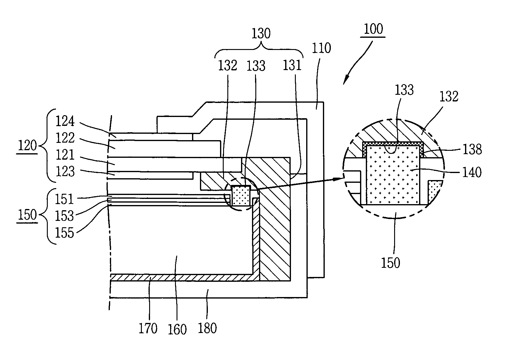
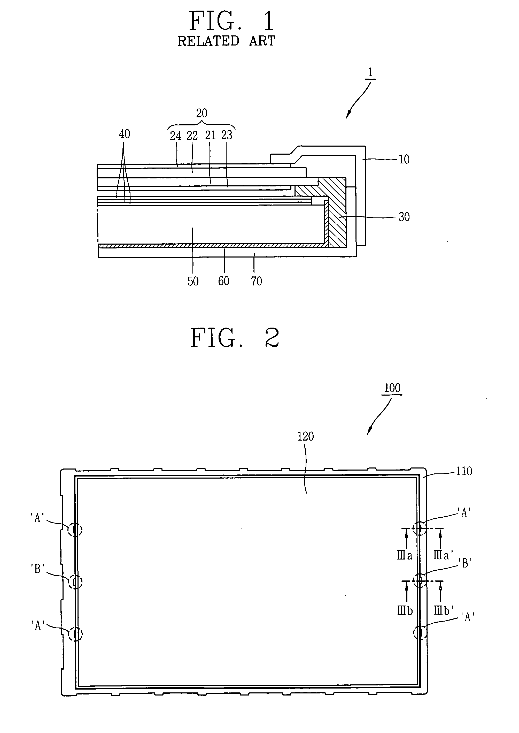
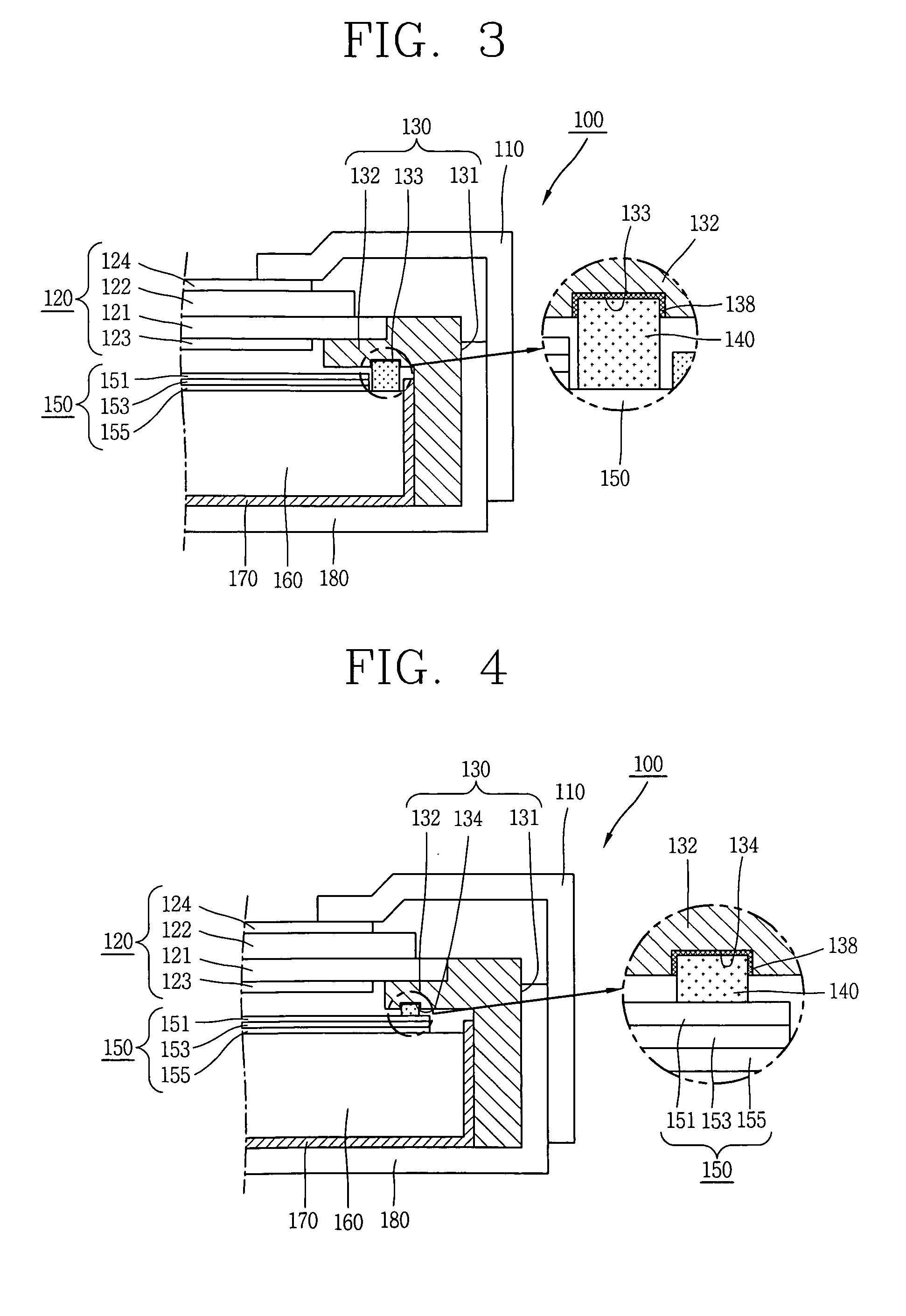
[0028]FIG. 2 is a planar view of an LCD device according to the present invention, FIG. 3 is a sectional view showing a first pad supporting portion, and FIG. 4 is a sectional view showing a second pad supporting portion.
[0029]As shown in FIGS. 2, 3 and 4, an LCD device 100 comprises an LCD panel 120 for forming an image, a main support 130 for supporting edges of the LCD panel 120, an optical sheet 150 disposed at a rear side of the main support 130, a light guide plate 160 disposed at a rear side of the optical sheet 150, an optical source (not shown) disposed at a side surface of the light guide plate 160, a reflection sheet 170 disposed at a rear side of the light guide plate 160, and top and bottom covers 110 and 180 coupled to each other for accommodating each of the components therein.
[0030]The top cover 110 is a structure for supporting edges of a front surface of the LCD panel 120. A display window through which an effective surface (a display region) of the LCD panel 120 i...
second embodiment
[0047]Hereinafter, an LCD device according to the present invention will be explained with reference to FIG. 7.
[0048]The same reference numerals as those of the first embodiment are given to the same parts as those of the second embodiment, and only differences from the first embodiment will be explained.
[0049]When compared with the LCD device according to the first embodiment, an LCD device 100 according to the second embodiment of the present invention further comprises a third pad supporting portion 135 and a third pad 148. The third pad supporting portion 135 is disposed on one surface of an extended portion 132 which is towards the LCD panel 120. The third pad supporting portion 135 is formed as a cavity for partially accommodating the third pad 148. The third pad 148 is disposed between the LCD panel 120 and the main support 130, thereby preventing movement of the LCD panel 120. One end of the third pad 148 contacts an edge of the LCD panel 120, and another end of the third pa...
third embodiment
[0051]Hereinafter, an LCD device according to the present invention will be explained with reference to FIGS. 8 and 9.
[0052]The same reference numerals as those of the first embodiment are given to the same parts as those of the third embodiment, and only differences from the first embodiment will be explained.
[0053]As shown in FIG. 8, an LCD device 100 according to the third embodiment of the present invention includes a pad and a pad supporting portion having different structures and shapes from those of the first embodiment.
[0054]Hereinafter, different structures and shapes of the LCD device 100 according to the third embodiment from those of the first embodiment will be explained by taking an example of a first pad 140 and a first pad supporting portion 133.
[0055]The first pad supporting portion 133 of the third embodiment includes a first pad protrusion portion protruded from one surface of an extended portion 132 towards a light guide plate 160, and the first pad 140 includes ...
PUM
 Abstract
Description
Claims
Application Information
 - Generate Ideas
- Intellectual Property
- Life Sciences
- Materials
- Tech Scout
- Unparalleled Data Quality
- Higher Quality Content
- 60% Fewer Hallucinations
Browse by: Latest US Patents, China's latest patents, Technical Efficacy Thesaurus, Application Domain, Technology Topic, Popular Technical Reports.
© 2025 PatSnap. All rights reserved.Legal|Privacy policy|Modern Slavery Act Transparency Statement|Sitemap|About US| Contact US: help@patsnap.com