Flexible print circuit and liquid crystal display device

a printing circuit and liquid crystal display technology, applied in static indicating devices, inspection/indentification of circuits, instruments, etc., can solve problems such as workability problems, misalignment of position, and increase of device size, so as to achieve convenient positioning operation, suppress peeling off of electrode pads, and easy operation

Inactive Publication Date: 2008-11-27
FUNAI ELECTRIC CO LTD
View PDF8 Cites 9 Cited by
  • Summary
  • Abstract
  • Description
  • Claims
  • Application Information

AI Technical Summary

Benefits of technology

[0016]In view of the above described problems, it is an object of the present invention to provide a flexible print circuit which positioning operation can be easily performed when the electrode pads which are formed in two flexible print circuits are bonded together and peeling off of the electrode pads can be suppressed. Further, it is another object of the present invention to provide a flexible print circuit which positioning operation can be easily performed when the electrode pads which are formed in two flexible print circuits are bonded together and a countermeasure for breaking of the wiring which is connected to the electrode pads, is prepared. In addition, it is other object of the present invention to provide a liquid crystal display device which can reduce a load for manufacturing operation and can suppress a production cost by including the above described flexible print circuit.

Problems solved by technology

Because two FPCs 102, 103 which have flexibility are bonded, misalignment of position tends to be generated when the two FPCs 102, 103 are bonded, and it causes a problem of workability.
However, in case of the above described method, because it becomes necessary to set up the holes, large spaces for the FPCs 102, 103 are required, and it causes problems of the increase of the device size, and increase of production cost.
However, in the case where the silk printing is performed, it is not preferable that it causes increase of production cost because material which is not used in the past, is required and additional material cost becomes necessary.
As a result, it causes a problem that they can be easily peeled off by heat or stress.
Further, it also causes a problem that possibility of breaking of the wirings which are connected to the first electrode pads 110 tends to be higher by a load that is applied to the FPC in relation to the fact that the first electrode pads 110 are not covered with the protection film and are exposed.
As a result, in the case where the two FPCs are connected, it is necessary to solve such problems, too, so it is not enough to set up only the positioning pattern as disclosed in JP-A-H11-121894.

Method used


Image

  • Flexible print circuit and liquid crystal display device
  • Flexible print circuit and liquid crystal display device
  • Flexible print circuit and liquid crystal display device

Examples


first embodiment

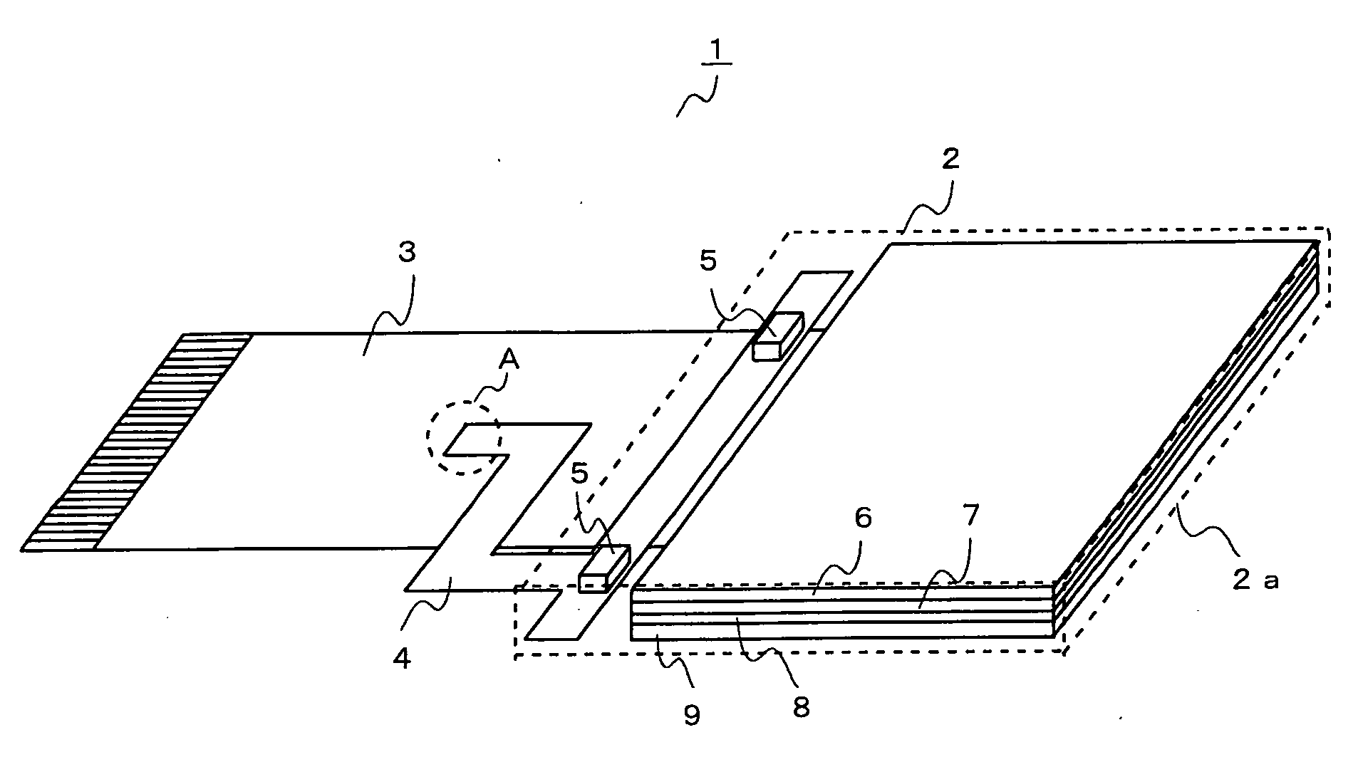
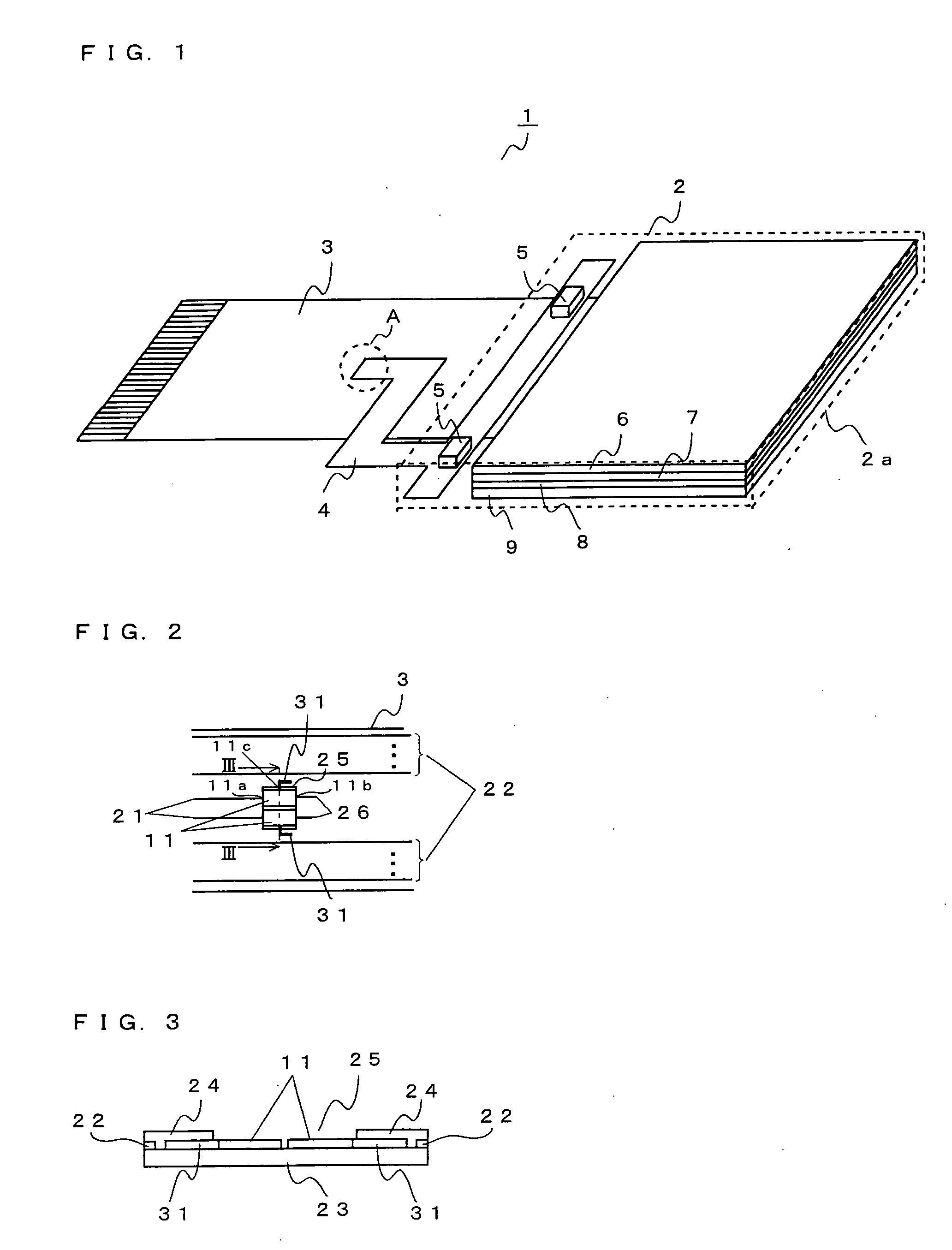
[0040]FIG. 1 is a schematic perspective view to show structure of a first embodiment of a liquid crystal display device which is provided with a flexible print circuit (FPC) in accordance with the present invention. FIG. 1 is a diagram when the liquid crystal display device 1 is viewed from reverse surface side (reverse side of a side where a liquid crystal display surface 2a can be seen). The liquid crystal display device 1 according to the first embodiment is provided with a liquid crystal display portion 2, a first FPC 3, and a second FPC 4. In the liquid crystal display portion 2, back light sources 5, a reflection sheet 6, a light guide plate 7, an optical sheet 8, and a liquid crystal panel 9 are included as shown in FIG. 1.

[0041]The first FPC 3 has wirings to drive the back light sources 5 and the liquid crystal panel 9 and one ends of these wirings are connected to an external connector which is not shown. Further, the other ends of the wirings to drive the back light source...

second embodiment

[0059]Next, explanation will be given about a second embodiment of a flexible print circuit in accordance with the present invention. In this embodiment, too, explanation will be given about a flexible print circuit (FPC) which is included in the liquid crystal display device by way of example as well as the first embodiment. Structure of the liquid crystal display device 1 according to the second embodiment is similar to that of the first embodiment except structure of the first FPC 3, therefore, explanation will be omitted for the same portions as the first embodiment. Further, in the explanation, same reference numeral will be given to the same portions as the first embodiment.

[0060]FIG. 6 is a diagram to explain structure of the first FPC 3 which is included in the liquid crystal display device 1 according to the second embodiment. In the first FPC 3 according to the second embodiment, wirings 21, 22 which are made of, for example, copper or the like, and first electrode pads 11...


PUM

PropertyMeasurementUnit
flexibleaaaaaaaaaa
brightnessaaaaaaaaaa
flexibilityaaaaaaaaaa

Abstract

A first electrode pad which is connected to a prescribed wiring and is exposed without being covered with a protection film, is formed in a flexible print circuit (FPC). The first electrode pad is set up to be bonded with a second electrode pad which is included in the other FPC. A positioning pattern which is made of the same material as the first electrode pad, and which is used as a marker to position the other flexible print circuit when the first electrode pad and the second electrode pad are bonded together, is extended from the first electrode pad.

Description

[0001]This application is based on Japanese Patent Application No. 2007-136297 filed on May 23, 2007, and the contents of which are hereby incorporated by reference.BACKGROUND OF THE INVENTION[0002]1. Field of the Invention[0003]The present invention relates to a flexible print circuit, and in particular, the present invention relates to structure of a flexible print circuit which is used in bonded with other flexible print circuit. Further, the present invention relates to a liquid crystal display device which is provided with such flexible print circuit.[0004]2. Description of Related Art[0005]Heretofore, two flexible print circuits (FPCs) have been positioned to be bonded. As one example of positioning two FPCs to be bonded, a liquid crystal display device will be explained by way of example. FIG. 8A and FIG. 8B are diagrams to show structure of a conventional liquid crystal display device, FIG. 8A is a schematic plan view of a liquid crystal display device when viewed from a fro...

Claims


Application Information

Patent Timeline
Patent Type & Authority Applications(United States)
IPC IPC(8): G02F1/133H05K1/02
CPCH05K1/0269H05K3/363H05K2201/058H05K2201/09781H05K2201/09918H05K2203/166
Inventor SAKIKUBO, TAKAYUKI
Owner FUNAI ELECTRIC CO LTD
Why Eureka
Try Eureka