Optical Pattern Generator Using a Single Rotating Optical Component with Ray-Symmetry-Induced Image Stability

a technology of optical pattern generator and rotating optical component, which is applied in the field of optical pattern generator with ray-symmetry-induced image stability, can solve the problems of limiting the scan rate, unsuitable for certain applications, and restricting the patterns that can be generated, so as to reduce thermal blooming and reduce the speed or radiometric efficiency of the system

Active Publication Date: 2008-11-27
SOLTA MEDICAL
View PDF20 Cites 7 Cited by
  • Summary
  • Abstract
  • Description
  • Claims
  • Application Information

AI Technical Summary

Benefits of technology

[0022]To reduce thermal blooming or other unwanted effects due to the sequential irradiation of adjacent image points, the sectors on the rotating component can be designed such that non-neighboring poi

Problems solved by technology

However, optical pattern generators based on tilting mirrors typically have characteristics that make them unsuitable for certain applications.
This takes time, which limits the scan rate.
However, this severely restricts the patterns that can be generated.
For example, it is difficult to generate irregular patterns since the mirror motion is constrained to be oscillatory.
The near-resonance condition also limits the range of scan rates that can be achieved.
For example, it is difficult to tune such a system over a wide range of scan rates since the near-resonance condition cannot be met over a wide range.
In addition, the angular scan velocity of resonant scanners is usually sinusoidal and not suitable for a large number of applications where dwell time at each point must be reasonably

Method used


Image

  • Optical Pattern Generator Using a Single Rotating Optical Component with Ray-Symmetry-Induced Image Stability
  • Optical Pattern Generator Using a Single Rotating Optical Component with Ray-Symmetry-Induced Image Stability
  • Optical Pattern Generator Using a Single Rotating Optical Component with Ray-Symmetry-Induced Image Stability

Examples


Embodiment Construction

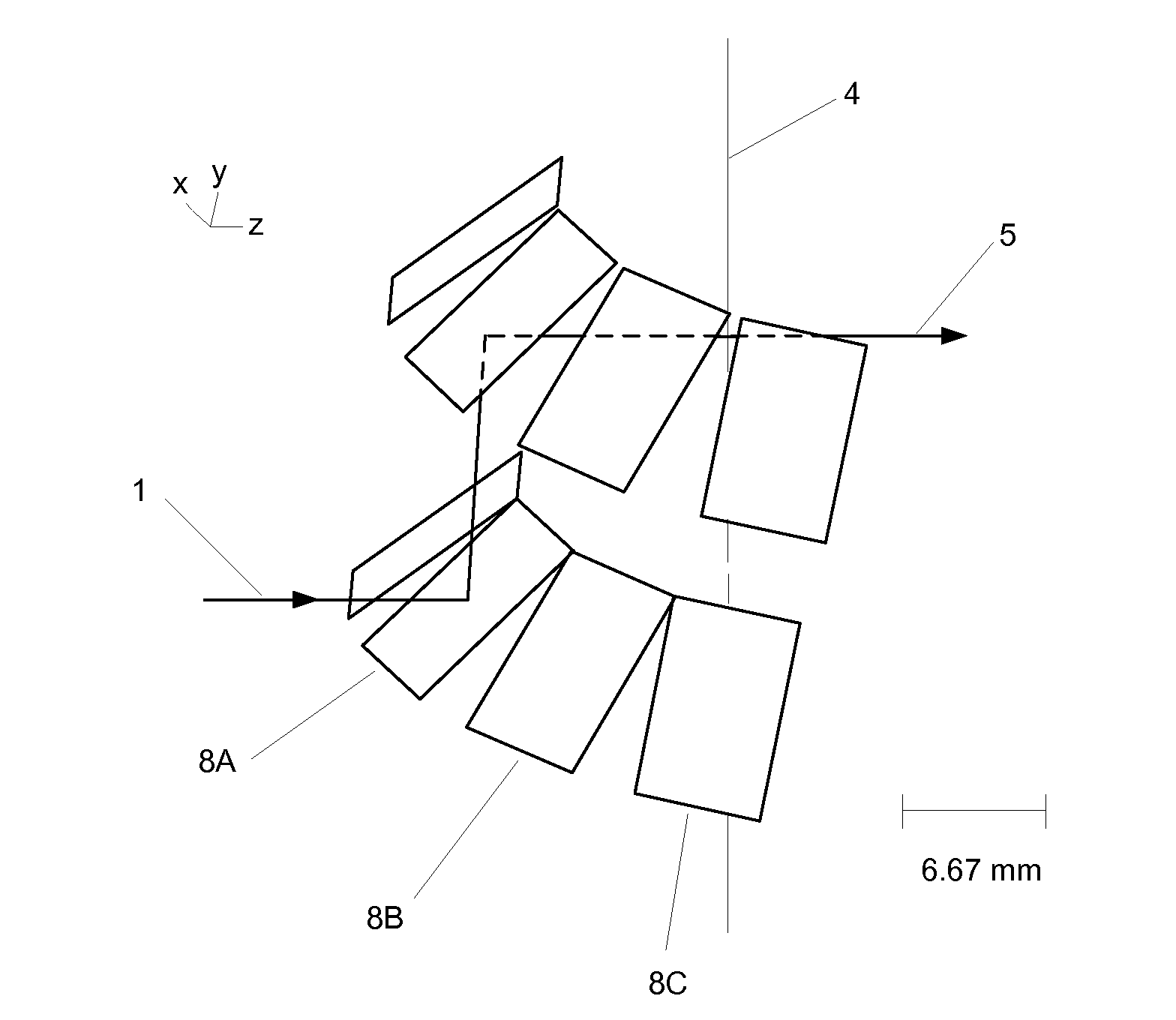
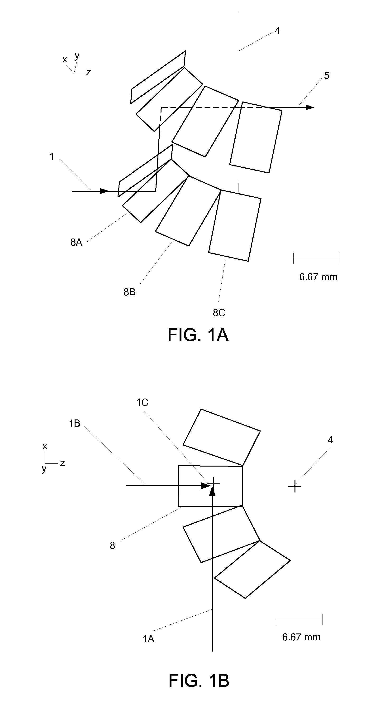
[0037]FIG. 1A is a diagram of an optical pattern generator illustrating various aspects of the invention. In this example, a rotating component 9 is divided into many sectors 8A, 8B, 8C, etc., which are arranged in a circle centered on the rotation axis 4 of the rotating component 9. An optical beam 1 is incident on the different sectors 8 as they rotate through the beam. At least a majority of the sectors 8 includes optical elements that are substantially gut-ray symmetric in the plane comprising the axis of rotation and the direction of the incident gut ray, as the rotating component 9 is rotated around its axis of rotation 4 and the sector 8 rotates through the incident optical beam 1.

[0038]As the component 9 rotates, the sectors 8 rotate through the incident optical beam 1. The point where a sector 8 is mid-way through its rotation through the optical beam 1 will be referred to as the mid-rotation position or mid-rotation angle. Each sector 8 deflects the incoming optical beam 1...


PUM


Abstract

An optical pattern generator uses a rotating component that includes a number of deflection sectors containing optical elements. Each sector deflects an incident optical beam by a substantially constant angle although this angle may vary from one sector to the next. The constant deflection angle is achieved by symmetry within the deflection sector, specifically gut-ray symmetry. The rotating component may be combined with an imaging group that produces, for example, image points, spots, or lines displaced along a line locus. The image spots can also be displaced to either side of a line, for example by introducing a tilt in the orthogonal direction or by introducing light beams at various angles to the plane of symmetry.

Description

RELATED APPLICATION(S)[0001]This application claims priority under 35 U.S.C. §119(e) to U.S. Provisional Patent Application Ser. No. 60 / 939,149, “Optical Pattern Generator Using a Single Rotating Optical Component with Ray-Symmetry-Induced Image Stability,” filed May 21, 2007. The subject matter of the foregoing is incorporated herein by reference in its entirety.BACKGROUND OF THE INVENTION[0002]1. Field of the Invention[0003]This invention relates generally to optically generating a pattern of figures such as arrays of image points, spots, or lines. More particularly, this invention relates to generating such patterns using a single rotating component that has a plurality of deflection sectors that deflect an incident optical beam by various amounts.[0004]2. Description of the Related Art[0005]The optical generation of a pre-defined pattern of spots or scan lines is used in a variety of applications. Digital copiers, printers, fingerprint identification, hand-held bar code scanners...

Claims


Application Information

Patent Timeline
IPC IPC(8): G02B26/12
CPCG02B26/10G02B26/108G06K7/10693
Inventor BROOME, BARRY G.MYERS, THOMAS R.DEBENEDICTIS, LEONARD C.DEWEY, DAVID A.
Owner SOLTA MEDICAL
Why Eureka
Try Eureka