Eureka AIR delivers breakthrough ideas for toughest innovation challenges, trusted by R&D personnel around the world.

Device select system for multi-device electronic system

a select system and electronic system technology, applied in the field of select system, can solve the problems of increasing the number of leads in the cable, affecting the bandwidth of the actuator, and increasing the complexity of the cable,

Inactive Publication Date: 2008-11-27
GLOBALFOUNDRIES INC
View PDF23 Cites 37 Cited by
  • Summary
  • Abstract
  • Description
  • Claims
  • Application Information

AI Technical Summary

Benefits of technology

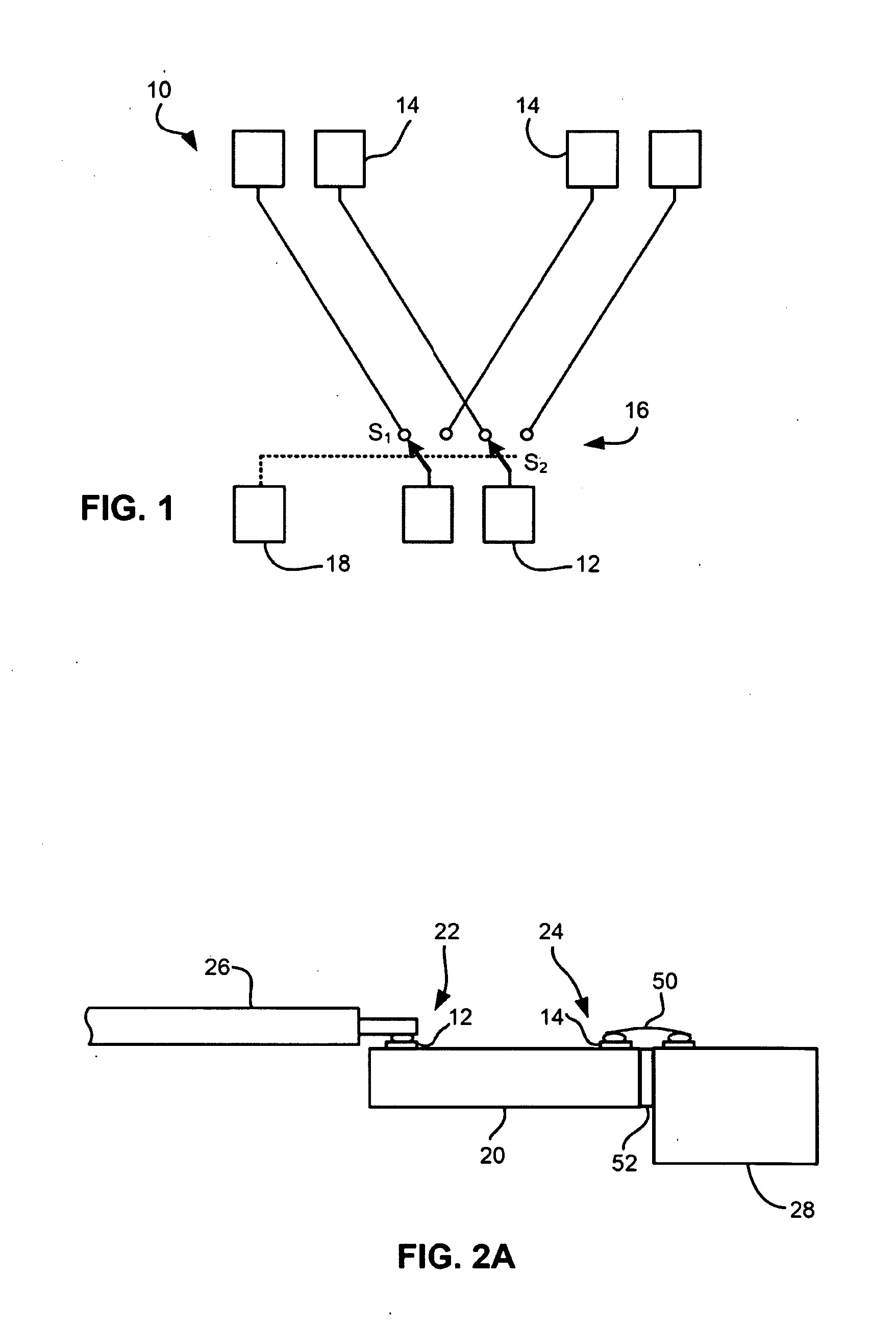
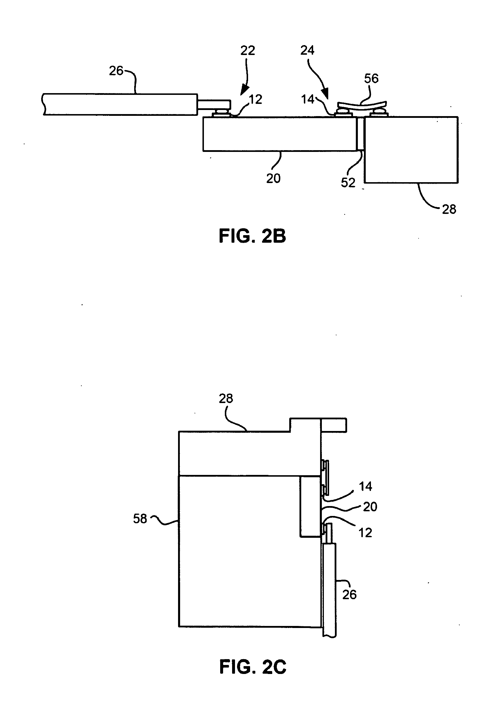
[0007]In one general embodiment, a system includes a first device on a first substrate; a second device on a second substrate; and a device select system coupled to the first and second devices. The device select system includes: a first portion having an array of first electrical contacts; a second portion having an array of second electrical contacts, there being more second electrical contacts than first electrical contacts, the second portion being coupled to the first and second devices, each of the first electrical contacts being associated with at least two of the second electrical contacts; and a select mechanism for selectively placing each of the first electrical contacts in electrical communication with one of the second electrical contacts associated therewith.

Problems solved by technology

One problem that arises is that cables tend to get more complex and costly as the number of devices in the head, and therefore the number of leads in the cable, increases.
Further, cables tend to get wider, and thus stiffer and more massive as the number of leads increases, which in turn can negatively affect actuator bandwidth and make cable routing for freedom of motion more difficult.
Generally, shrinking the dimensions of the leads in the cable is not an option, as DC resistance and AC impedance would also change undesirably.
Current technology fails to address tape head cabling problems that will be posed by bourgeoning I / O needs for future multi-track, multi-format or multi-function tape heads.

Method used


Image

  • Device select system for multi-device electronic system
  • Device select system for multi-device electronic system
  • Device select system for multi-device electronic system

Examples


Embodiment Construction

[0039]The following description is the best mode presently contemplated for carrying out the present invention. This description is made for the purpose of illustrating the general principles of the present invention and is not meant to limit the inventive concepts claimed herein. Further, particular features described herein can be used in combination with other described features in each of the various possible combinations and permutations.

[0040]In the drawings, like and equivalent elements are numbered the same throughout the various figures.

[0041]It must also be noted that, as used in the specification and the appended claims, the singular forms “a,”“an” and “the” include plural referents unless otherwise specified.

[0042]The embodiments described below disclose a new device select system that allows selective creation of electrical connections between electrical contacts for such things as selecting particular groups of devices and not others. Moreover, various embodiments allo...


PUM

PropertyMeasurementUnit
resistanceaaaaaaaaaa
DC coil resistanceaaaaaaaaaa
frequencyaaaaaaaaaa

Abstract

In one general embodiment, a system includes a first device on a first substrate; a second device on a second substrate; and a device select system coupled to the first and second devices. The device select system includes: a first portion having an array of first electrical contacts; a second portion having an array of second electrical contacts, there being more second electrical contacts than first electrical contacts, the second portion being coupled to the first and second devices, each of the first electrical contacts being associated with at least two of the second electrical contacts; and a select mechanism for selectively placing each of the first electrical contacts in electrical communication with one of the second electrical contacts associated therewith.

Description

RELATED APPLICATIONS[0001]This application is a continuation in part of U.S. patent application Ser. No. 11 / 734,634, filed Apr. 12, 2007, and which is incorporated by reference.BACKGROUND OF THE INVENTION[0002]The present invention relates to device select systems, and more particularly, this invention relates to a device select system and methods for selecting devices on multiple magnetic heads.[0003]Business, science and entertainment applications depend upon computers to process and record data, often with large volumes of the data being stored or transferred to nonvolatile storage media, such as magnetic discs, magnetic tape cartridges, optical disk cartridges, floppy diskettes, or floptical diskettes. Typically, magnetic tape is the most economical means of storing or archiving the data. Storage technology is continually pushed to increase storage capacity and storage reliability. Improvement in data storage densities in magnetic storage media, for example, has resulted from im...

Claims


Application Information

Patent Timeline
Patent Type & Authority Applications(United States)
IPC IPC(8): G11B21/02
CPCG11B15/06G11B15/087G11B15/1825G11B5/17G11B15/602H03K17/002H03K17/56G11B15/467
Inventor BISKEBORN, ROBERT GLENNTRETTER, LARRY LEEROY
Owner GLOBALFOUNDRIES INC
Why Eureka
Eureka Blog
Learn More