Method and apparatus for cooling electronic equipment

a technology for electronic equipment and cooling equipment, applied in lighting and heating equipment, space heating and ventilation control systems, heating types, etc., can solve problems such as increased heat dissipation, components and related electronic equipment in the server room may be damaged or operated incorrectly, and increase heat dissipation

Active Publication Date: 2008-11-27
ORACLE INT CORP
View PDF9 Cites 137 Cited by
  • Summary
  • Abstract
  • Description
  • Claims
  • Application Information

AI Technical Summary

Benefits of technology

[0008]In general, in one aspect, one or more embodiments of the invention relate to a method for cooling electronic equipment, comprising: propagating air through a first electronic component of the electronic equipment into a first enclosed area, wherein propagating the air through the first electronic component cools the first electronic component, circulating a refrigerant in a cooling loop, wherein the cooling loop comprises a heat exchanger, and propagating the air out of the first enclosed area by passing through the heat exchanger into a second enclosed area, wherein the air is cooled by passing through the heat exchanger.

Problems solved by technology

An important issue regarding server rooms and server operation involves temperature.
As those skilled in the art will note, computer operation results in heat dissipation.
In a server room, many electronic components are be operating at the same time, and thus, without adequate cooling, the components and related electronic equipment in the server room may be damaged or operate incorrectly as a result of high temperatures.
As servers and related electronic equipment become more powerful, heat dissipation increases.
In other words, as servers and related electronic equipment continue to improve in terms of density, computing speed, and performance, more energy is released, thereby resulting in increased heat dissipation.
Using only an air cooling technique to cool a server room having such increased heat dissipation requires the consideration of several issues.
Further, the increased volume of air flow that would be required to cool the server room might render the server room uncomfortable for operators and technicians in the server room.

Method used


Image

  • Method and apparatus for cooling electronic equipment
  • Method and apparatus for cooling electronic equipment
  • Method and apparatus for cooling electronic equipment

Examples


Embodiment Construction

[0024]Specific embodiments of the invention will now be described in detail with reference to the accompanying figures. Like elements in the various figures are denoted by like reference numerals for consistency. Further, the use of “ST” in the figures is equivalent to the use of “Step” in the detailed description below.

[0025]In the following detailed description of embodiments of the invention, numerous specific details are set forth in order to provide a more thorough understanding of the invention. However, it will be apparent to one of ordinary skill in the art that the invention may be practiced without these specific details. In other instances, well-known features have not been described in detail to avoid unnecessarily complicating the description.

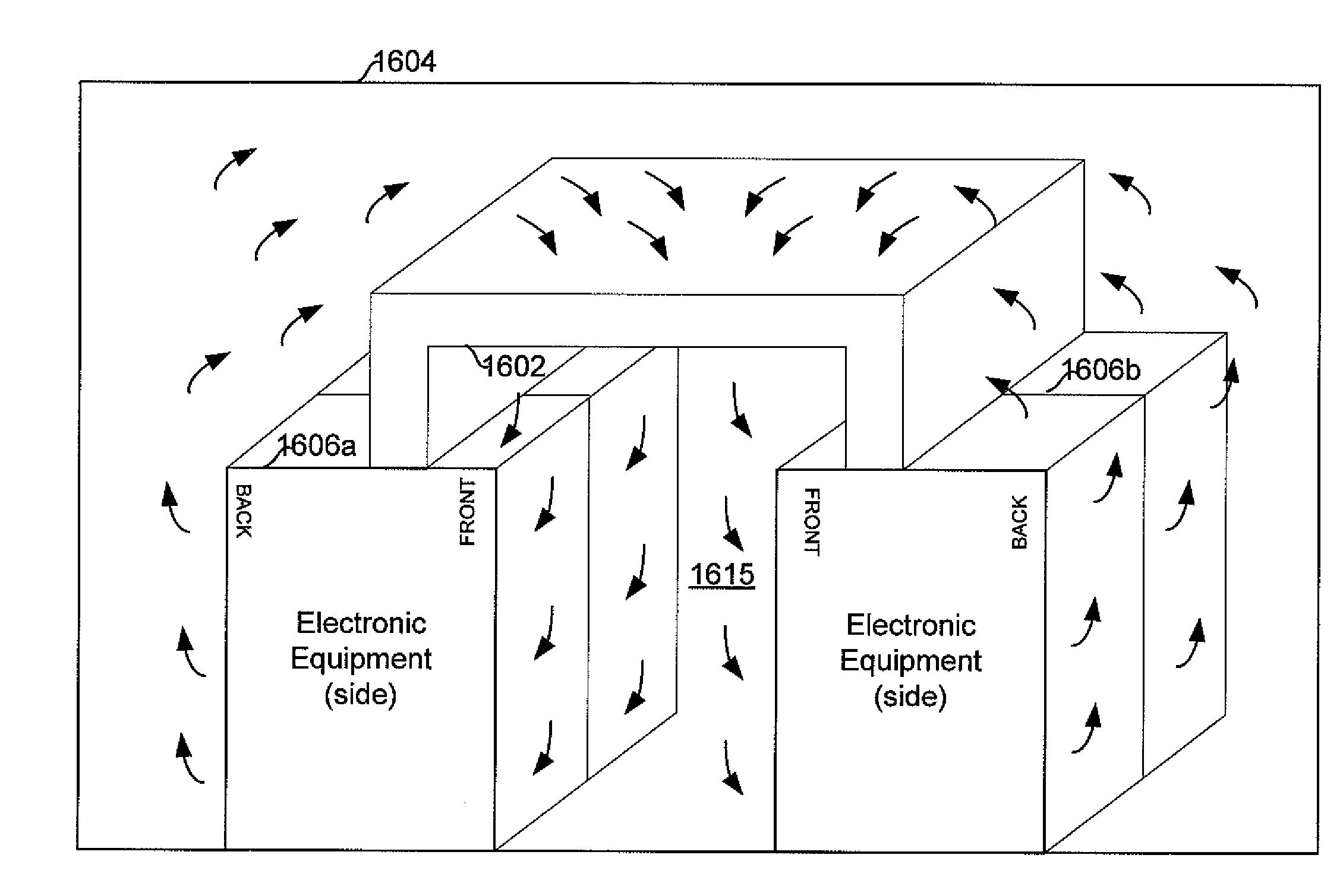
[0026]Embodiments of the invention relate to methods and apparatus for cooling electronic equipment. More specifically, one or more embodiments of the invention relate to methods and apparatus for cooling electronic equipment using...


PUM


Abstract

A method for cooling electronic equipment. The method including propagating air through a first electronic component of the electronic equipment into a first enclosed area, where propagating the air through the first electronic component cools the first electronic component, circulating a refrigerant in a cooling loop, where the cooling loop comprises a heat exchanger, and propagating the air out of the first enclosed area by passing through the heat exchanger into a second enclosed area, where the air is cooled by passing through the heat exchanger.

Description

BACKGROUND[0001]A computer system frequently needs data and / or services from another computer system. For example, a bank customer may request to see his current bank account information on his home computer system, which obtains the requested information from a computer system maintained by and located at the bank. In such arrangements, the computer system requesting the data and / or service is referred to and known as the “client” system, and the computer system servicing the request is referred to and known as the “server” system.[0002]Many entities, for various reasons, situate groups of servers and related electronic equipment in “server rooms” or “data centers.” Within a server room, several servers may be positioned vertically atop one another (with spacing) using a “rack.” Racks of servers, memory units, power supplies, computers, etc. (hereinafter generally referred to as “electronic equipment”) are often housed or enclosed in housings known as “cabinets” that provide protec...

Claims


Application Information

Patent Timeline
Patent Type & Authority Applications(United States)
IPC IPC(8): H05K7/20F24F1/0063
CPCF24F1/0059F24F5/0089F24F5/0092F24F11/0001F24F2221/14H05K7/20745H05K7/2079F24F1/0063
Inventor NELSON, DEAN H.BECHTOLSHEIM, ANDREAS V.RYAN, MICHAEL C.
Owner ORACLE INT CORP
Why Eureka
Try Eureka