
Multiple-input multiple-output communication method and multiple-input multiple-output communication system of enabling the method

a communication system and multi-input technology, applied in the field of multi-user multipleinput multipleoutput (mimo) communication, can solve problems such as increase the overhead of the communication system, error in a preceding process, etc., and achieve the effect of effective transmission of more data

Active Publication Date: 2008-11-27
SAMSUNG ELECTRONICS CO LTD +1
View PDF8 Cites 68 Cited by
  • Summary
  • Abstract
  • Description
  • Claims
  • Application Information

AI Technical Summary

Benefits of technology

The invention provides a MIMO communication system and method that can adjust the number of transmitting antennas based on the power of the transmission signal, resulting in more efficient data transmission. It also improves the data transmission rate even when the power of the transmission signal is relatively high. The system can use a smaller number of transmitting antennas to improve data transmission, and can improve the data transmission rate even when the signal-to-noise ratio is increased. The system can also use a relatively smaller number of transmitting antennas and improve data transmission rate while using fewer hardware resources. The invention also provides a communication environment where interference is relatively less. Overall, the invention enhances the efficiency and performance of MIMO communication.

Problems solved by technology

Accordingly, an error occurs in a preceding process due to the difference.
However, when the amount of feedback channel information increases, it also may increase overhead in the communication system.

Method used


Image

  • Multiple-input multiple-output communication method and multiple-input multiple-output communication system of enabling the method
  • Multiple-input multiple-output communication method and multiple-input multiple-output communication system of enabling the method
  • Multiple-input multiple-output communication method and multiple-input multiple-output communication system of enabling the method

Examples


Embodiment Construction

[0029]Reference will now be made in detail to the present embodiments of the present invention, examples of which are illustrated in the accompanying drawings, wherein like reference numerals refer to the like elements throughout. The embodiments are described below in order to explain the present invention by referring to the figures.

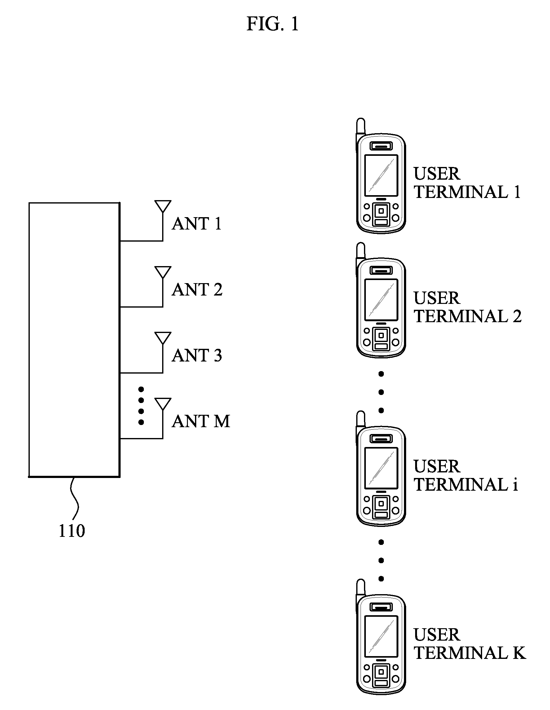
[0030]FIG. 1 shows an example of a Multiple-Input Multiple-Output (MIMO) communication system according to an embodiment of the invention. A base station 110 includes M transmitting antennas (ANT 1, ANT 2, ANT 3, . . . , ANT M). K user terminals (user terminal 1, user terminal 2, user terminal 3, . . . , user terminal K) are also provided.

[0031]A channel is formed between each of the antennas and each of the user terminals for data communication. Generally, the channel may be represented as a channel matrix H. A relationship between a received signal of a user terminal side and a transmission signal of a transmitting antenna side is represented by the ...


PUM


Abstract

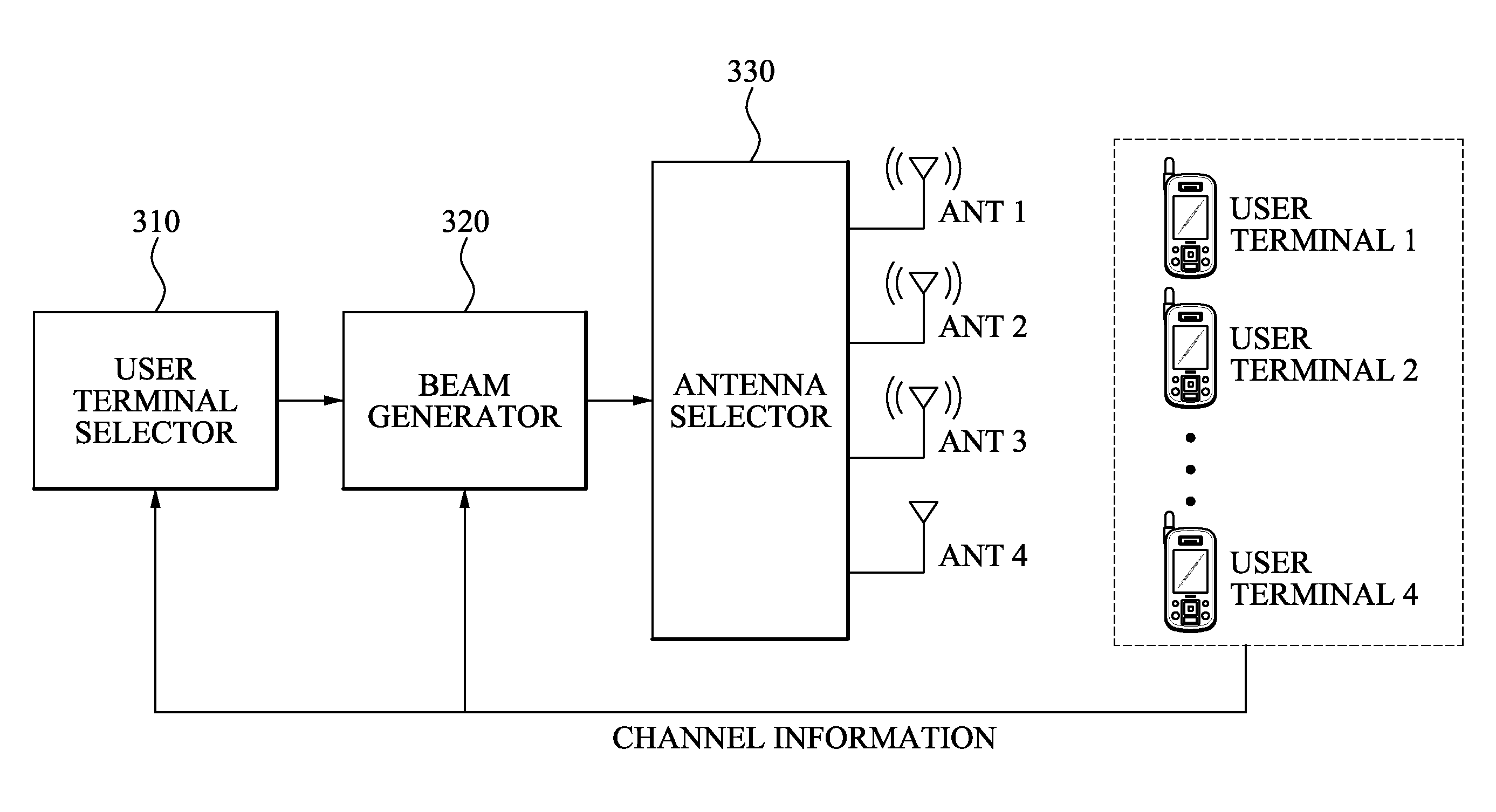
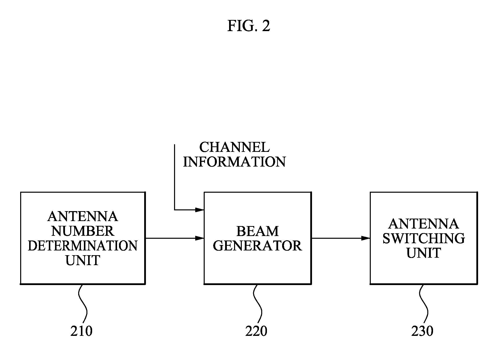
A Multiple-Input Multiple-Output (MIMO) communication system and method. The MIMO communication system includes: an antenna number determination unit to determine a number of active antennas among a plurality of transmitting antennas based on a power of a transmission signal wherein the number of active antennas is at least one and the at least one active antenna transmits the transmission signal; and a beam generator to generate the transmission signal corresponding to the number of active antennas by using channel information wherein the channel information is fed back from each of a plurality of user terminals.

Description

CROSS-REFERENCE TO RELATED APPLICATIONS[0001]This application claims the benefit of a U.S. Provisional Application No. 60 / 939,765, filed in the U.S. Patent and Trademark Office on May 23, 2007, and of Korean Application No. 2007-56656, filed on Jun. 11, 2007, Korean Application No. 2007-101063, filed in the Korean Intellectual Property Office on Oct. 8, 2007, and Korean Application No. 2007-135843, filed in the Korean Intellectual Property Office on Dec. 21, 2007, the disclosures of which are incorporated herein by reference.BACKGROUND OF THE INVENTION[0002]1. Field of the Invention[0003]Aspects of the invention relate to a multi-user Multiple-Input Multiple-Output (MIMO) communication, and more particularly, to a MIMO communication system and method that can control a transmitting antenna based on a power of a transmission signal.[0004]2. Description of the Related Art[0005]Currently, research to provide a voice service and various types of multimedia services and to support high-q...

Claims


Application Information

Patent Timeline
Patent Type & Authority Applications(United States)
IPC IPC(8): H04L27/28H04M1/00
CPCH04B7/0452H04B7/0691
Inventor KIM, JUN MOPARK, CHANG SOONPARK, KI-HONGKO, YOUNG-CHAISUH, JUNG HOONKIM, SUNG JIN
Owner SAMSUNG ELECTRONICS CO LTD
Learn More