

Image capture environment calibration method and information processing apparatus
a calibration method and information processing technology, applied in the field of image capture environment calibration method and information processing apparatus, can solve the problems of often disabled appropriate calibration, achieve the effects of reducing input errors of image data, reducing calibration precision, and improving calibration precision
- Summary
- Abstract
- Description
- Claims
- Application Information
AI Technical Summary
Benefits of technology
Problems solved by technology
Method used
Image

Examples
first embodiment
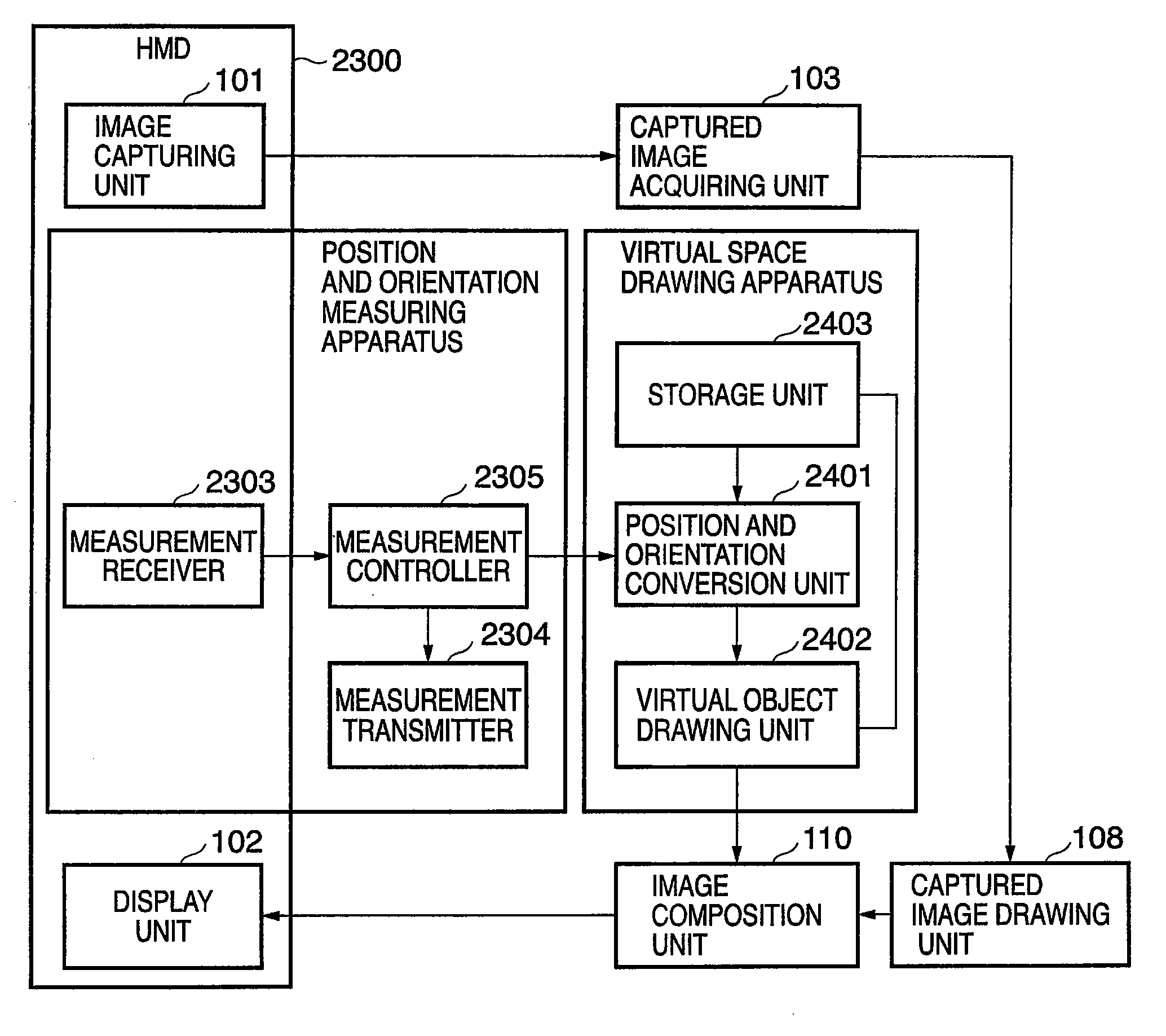
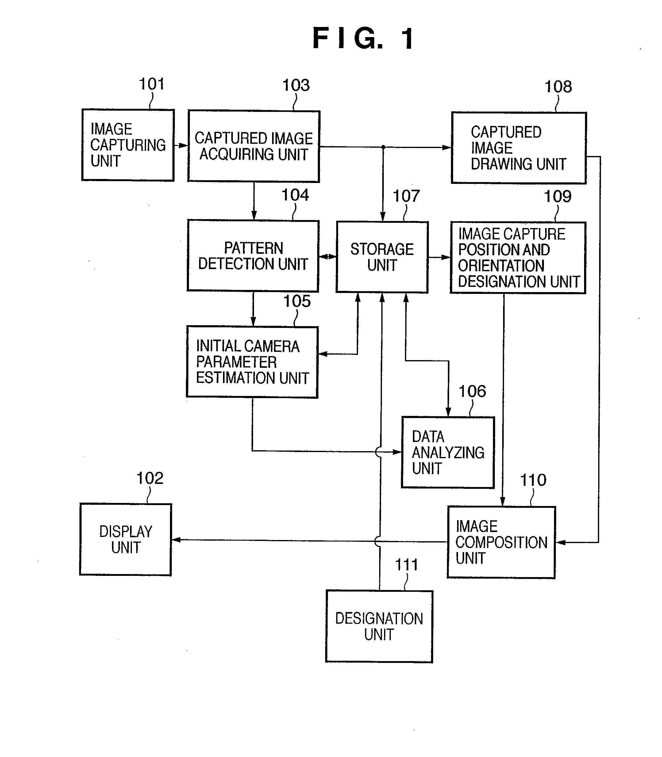
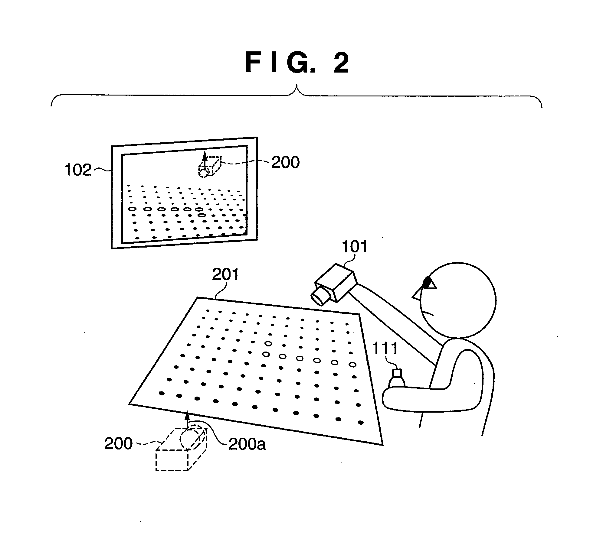
[0051]FIG. 1 is a block diagram showing the functional arrangement of a calibration apparatus according to the first embodiment, and FIG. 2 illustrates the use state of an image capture environment calibration method according to the first embodiment. In FIGS. 1 and 2, the same reference numerals denote the same components. FIG. 3 shows a calibration pattern according to the first embodiment.
[0052]In the following embodiments, calibration of image capturing unit unique information (camera intrinsic parameter calibration), or of geometric information associated with a physical space (marker calibration), or of the relationship between the image capturing unit and physical space (sensor calibration), is executed.
[0053]Reference numeral 101 denotes an image capturing unit, which uses a color CCD camera according to the embodiment. However, the present invention is not limited to the color CCD camera as the type of the image capturing unit 101. For example, the present invention can be ...
second embodiment
[0090]In the first embodiment, the current position and orientation of the image capturing unit 101 are converted into those on the polar coordinate system, and the converted position and orientation undergo rotation in the latitude direction and that about the axis of sighting of the image capturing unit 101 on the polar coordinate system, thus calculating the designation position and orientation. However, the present invention is not limited to such specific calculation method of the designation position and orientation, and may be applied to any other methods as long as they can calculate the designation positions and orientations so as to make the user capture a pattern from various directions. For example, a method of analyzing the vanishing point directions of the captured images stored in the storage unit 107 and calculating the designation position and orientation based on the analysis result may be used. The second embodiment will exemplify a case wherein this calculation m...
third embodiment
[0114]In the first embodiment, the image capture position and orientation are designated only after the initial camera parameters of the image capturing unit 101 are derived in step S403 in FIG. 4. However, the present invention is not limited to the calibration method and calibration order of derivation of the initial camera parameters and the like. For example, when the camera calibration has already been done using an image capturing device of the same model, and rough calibration values are stored, values close to the intrinsic parameters of the image capturing unit 101 to be used are calculated in advance. In this case, when the calibration pattern can be recognized, the camera extrinsic parameters may be derived without deriving the initial camera parameters. In this way, details of the processing sequence for calibrating the final camera intrinsic parameters based on the rough camera internal parameters acquired in advance will be described with reference to the flowchart of ...
PUM
 Abstract
Description
Claims
Application Information