
Linear motion guide apparatus

Inactive Publication Date: 2008-11-27
HIWIN TECH
View PDF8 Cites 26 Cited by
  • Summary
  • Abstract
  • Description
  • Claims
  • Application Information

AI Technical Summary

Benefits of technology

[0013]The primary objective of the present invention is to provide a linear motion guide apparatus including one or more holding devices and one or more retaining devices attachable to the slider for retaining the rolling or bearing device to the slider together with the end cap and for preventing the holding devices and the retaining devices and the rolling or bearing device from being disengaged from the slider and the end cap.
[0014]The other objective of the present invention is to provide a linear motion guide apparatus including one or more holding devices and one or more retaining devices arranged to be easily molded or manufactured.
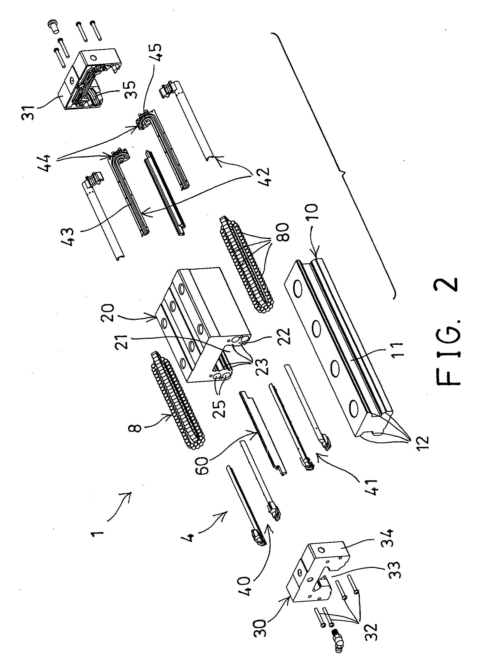
[0015]In accordance with one aspect of the invention, there is provided a linear motion guide apparatus comprising a guide rail including two side portions facing outwardly and including two inclined surfaces formed in each of the side portions, a slider slidably attached onto the guide rail and movable along the guide rail, the slider including a concave for forming two legs and for slidably receiving and engaging onto the guide rail, and including two inclined surfaces formed on each of the legs and facing toward the inclined surfaces of the guide rail respectively for forming two fore-and-aft raceway grooves between each of the legs of the slider and the guide rail, and including two conduits formed through each of the legs, a first end cap and a second end cap attached to end portions of the slider, the first and the second end caps each including a concave for forming two legs and for slidably receiving and engaging onto the guide rail, and each including a turnaround formed in each of the legs of the first and the second end caps, two holding assemblies attached to the legs of the slider and the first and the second end caps respectively, and each of the holding assemblies including two L-shaped holding devices and a retaining device attached to the respective leg of the slider and the respective legs of the first and the second end caps for forming two endless ball guiding channels, and the holding devices of the holding assemblies each including two detachable halves for allowing the holding devices to be easily manufactured, and four chains of rolling members engaged through the endless ball guiding channels of the holding assemblies and engaged between the slider and the guide rail for facilitating a sliding movement between the slider and the guide rail.
[0016]The halves of each of the holding devices are detachably secured together with pegs and holes for allowing the holding devices to be easily and quickly molded.
[0017]The holding devices each include a tubular member engaged into the conduit of the slider and having a bore formed in the tubular member for receiving the rolling members, and each include an end member provided at one end of the tubular member for forming the L-shaped holding device, and the holding devices each include a curved ball return pathway formed in each of the end members and communicating with the bore of the tubular member for forming the endless ball guiding channels and for smoothly receiving the rolling members.

Problems solved by technology

However, the rolling or bearing members that are retained between the spacer members of the ball retainer members may not be easily engaged into the ball guide passages and / or the ball return passages of the movable block and the track rail after the rolling or bearing members have been assembled and engaged in and retained between the spacer members of the ball retainer members.
However, it will be inconvenient to assemble and engage the rolling or bearing members between the rolling element retainer segments, and the rolling element retainer segments may not be easily attached to or engaged into the outer housing.
However, the recirculating model includes a U-shaped structure that may not be easily molded and may not be easily disengaged from the molds after the molding operation, and the other molding problems may also be generated or occurred.

Method used


Image

  • Linear motion guide apparatus
  • Linear motion guide apparatus
  • Linear motion guide apparatus

Examples


Embodiment Construction

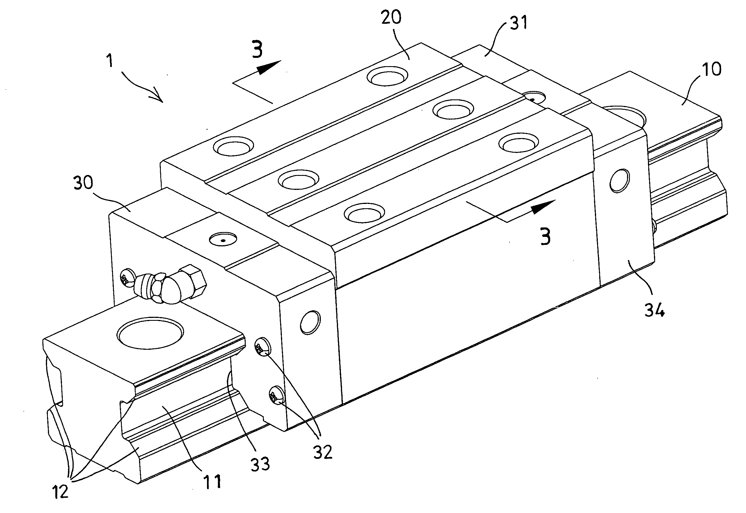
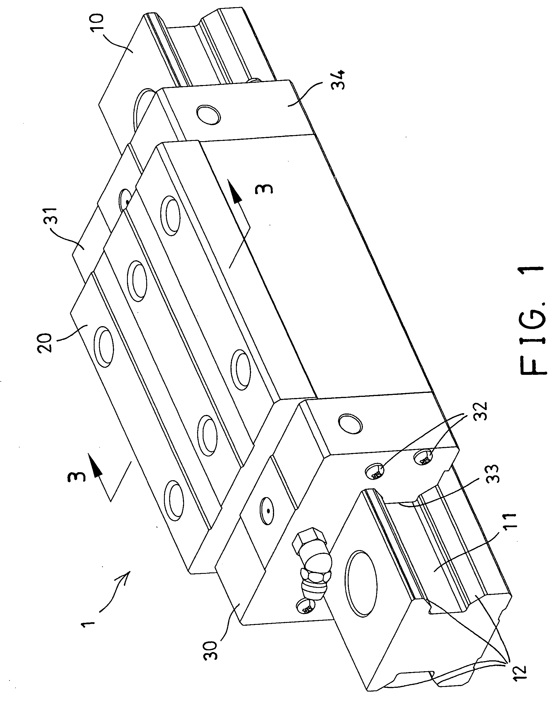
[0040]Referring to the drawings, and initially to FIGS. 1-3, a linear motion guide apparatus 1 in accordance with the present invention comprises a slide block or a slider 20 for slidably attaching onto a guide rail 10 and arranged to be moved along the guide rail, and normally, two end caps 30, 31 disposed on the two sides or end portions or outer portions of the slider 20 and attached or secured to the slider 20 with such as latches or fasteners 32 or the like. Two dust caps or wipers (not shown) may further be provided and disposed on the outer portions of the end caps 30, 31 and to be attached or secured onto the end caps 30, 31 with such as fasteners or latches (not shown) or the like. The guide rail 10 includes a longitudinal recess 11 formed in each of the two outer side portions thereof and facing outwardly, and includes two pairs or four inclined surfaces 12 formed and located on opposite sides of the longitudinal recesses 11 of the guide rail 10 respectively.

[0041]The slid...


PUM


Abstract

A linear motion guide device includes a slider and two end caps attached to side portions of the slider, and two holding assemblies attached to two side legs of the slider and the end caps for forming four endless ball guiding channels and for smoothly receiving four chains of rolling members, the holding assemblies each include two L-shaped holding devices and a retaining device attached to the leg of the slider and the end caps, and the holding devices each include two detachable halves for allowing the holding devices to be easily and quickly molded and for allowing the holding devices to be easily disengaged from the mold devices.

Description

BACKGROUND OF THE INVENTION[0001]1. Field of the Invention[0002]The present invention relates to a linear motion guide apparatus, and more particularly to a linear motion guide apparatus including one or more holding devices and one or more retaining devices attachable to the slider for retaining the rolling or bearing device to the slider together with the end cap and for preventing the holding devices and the retaining devices and the rolling or bearing device from being removed or disengaged from the slider and the end cap.[0003]2. Description of the Prior Art[0004]Typical linear motion guide devices comprise a slider or slide block slidably attached onto a guide rail, and normally, a rolling or bearing device disposed between the slider and the guide rail for facilitating the sliding movement between the slider and the guide rail and for allowing the slider and the guide rail to be smoothly moved relative to each other.[0005]For example, U.S. Pat. No. 5,947,605 to Shirai disclos...

Claims


Application Information

Patent Timeline
IPC IPC(8): F16C33/00
CPCF16C29/0602F16C29/065
Inventor CHEN, SCOTTECHEN, TSUNG JEN
Owner HIWIN TECH
Learn More