Automatic transfer method, transfer robot, and automatic transfer system

a transfer method and robot technology, applied in the direction of program control, total factory control, instruments, etc., can solve the problems of uniform operation and lack of flexibility in security operations, and achieve the effect of reducing energy consumption, facilitating energy-saving transfer, and facilitating the operation of security levels

Active Publication Date: 2008-11-27
PANASONIC CORP
View PDF17 Cites 37 Cited by
  • Summary
  • Abstract
  • Description
  • Claims
  • Application Information

AI Technical Summary

Benefits of technology

[0005]An object of the present invention is to realize dynamic and flexible operation of security levels in automatic transfer employing a transfer robot capable of autonomous movement.
[0009]According to the present invention, the security level of the transfer robot under movement is switched on the basis of surrounding environment and the like (specifically, the zone level defined beforehand by each region in the transfer route, the present position information of the transfer robot, the type information of the transferred object, and the like). This realizes dynamic and flexible operation of security levels. Then, when the security level is dynamically maintained in an optimal state, security is ensured with minimum energy. Thus, depending on the situation, efficient energy-saving transfer can also be achieved.

Problems solved by technology

Nevertheless, in conventional automatic transfer employing a transfer robot capable of autonomous movement including that disclosed in Japanese Laid-Open Patent Publication No. 2004-142070, operation with respect to security is uniform and lacks flexibility.

Method used


Image

  • Automatic transfer method, transfer robot, and automatic transfer system
  • Automatic transfer method, transfer robot, and automatic transfer system
  • Automatic transfer method, transfer robot, and automatic transfer system

Examples


first embodiment

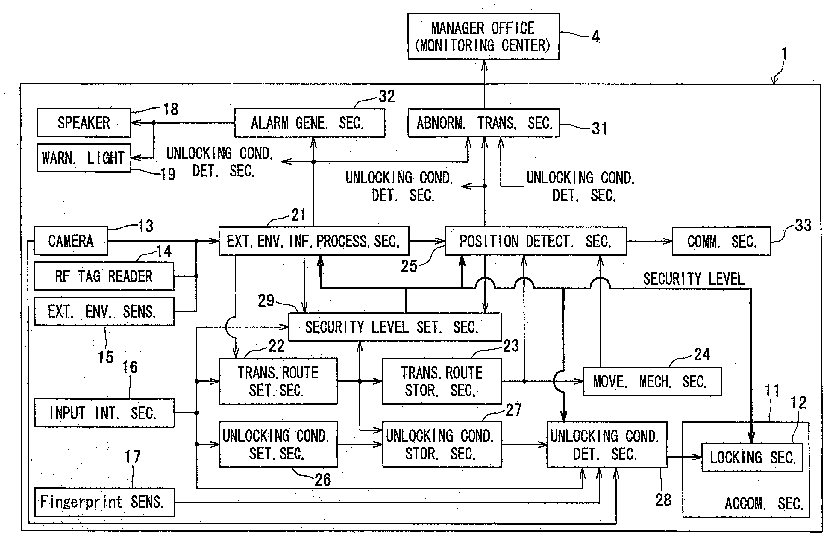
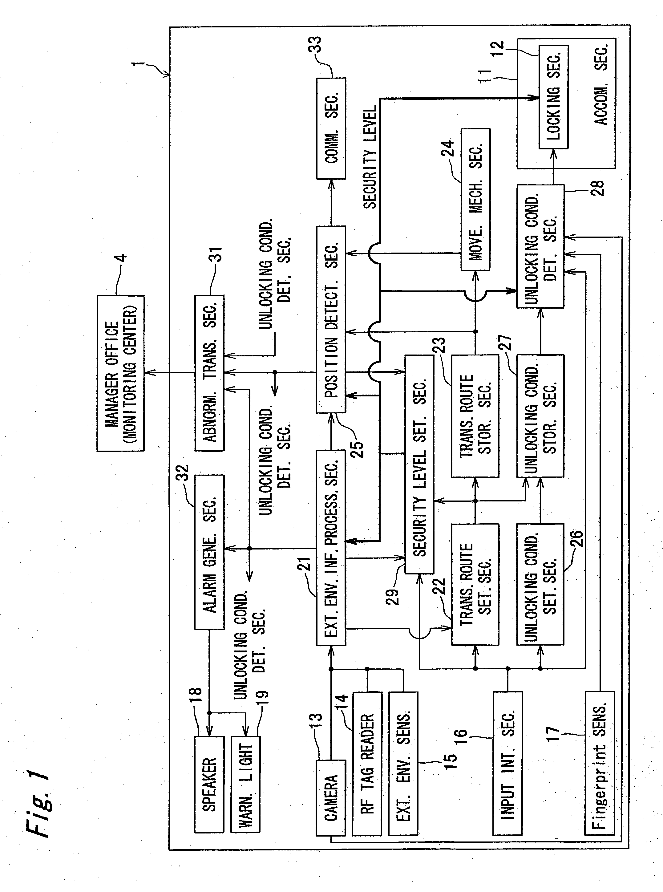
[0039]FIG. 1 shows a transfer robot 1 capable of autonomous movement according to an embodiment of the present invention. The present embodiment is described for a case that a transferred object is transferred in a condominium 2 shown in FIG. 2 by using a transfer robot 1.

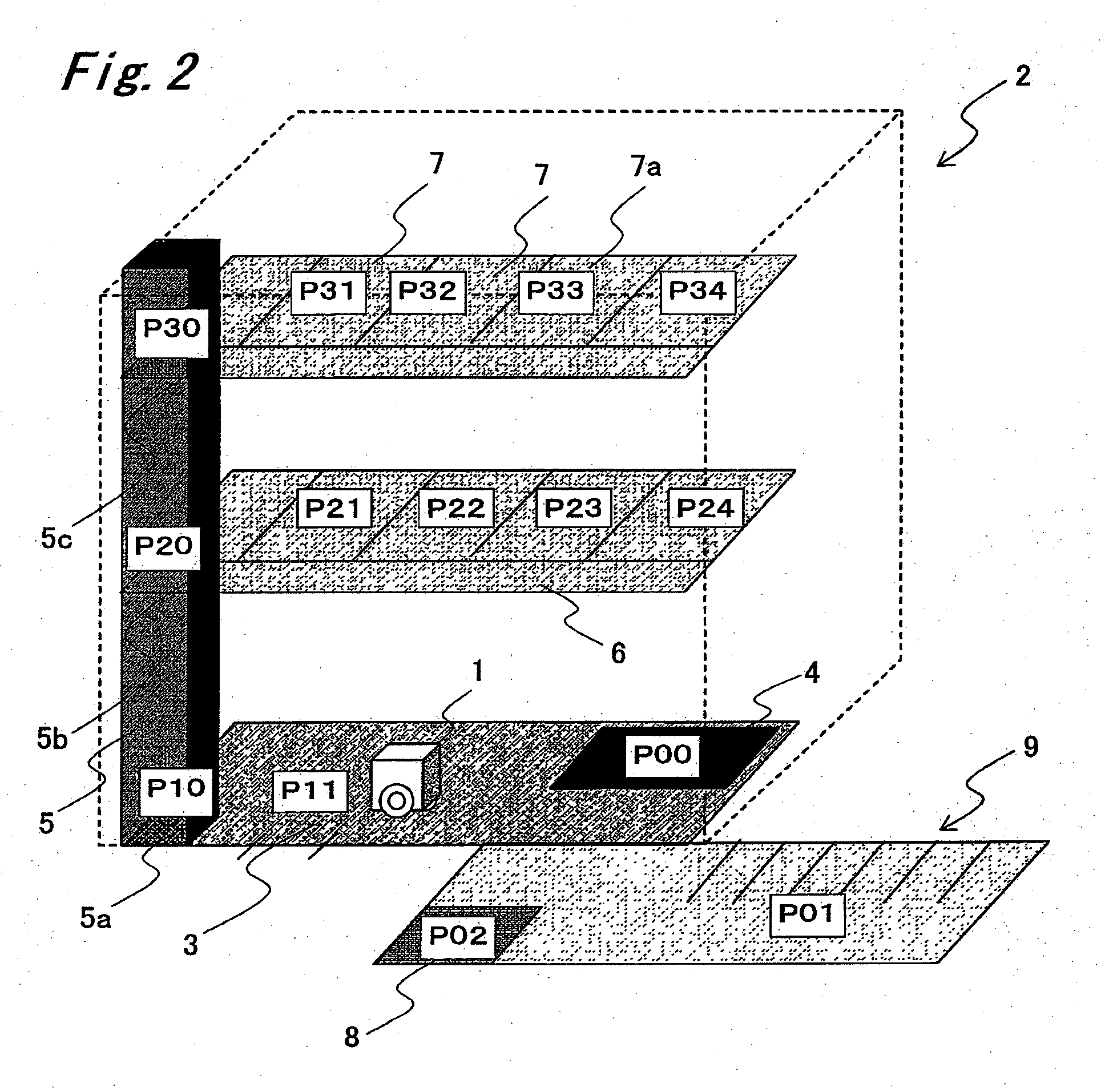
[0040]Referring to FIG. 2, on the first floor of the condominium 2, an entrance hall 3 and a building manager's office 4 serving as a monitoring center are arranged. First, a case is assumed that a resident, a visitor, a mail delivery person, a parcel delivery person, or the like enters or exits through the entrance hall 3. A building manager stays always in the building manager's office 4, and performs services (such as relay of a visitor and relay of parcel delivery service) for the residents of the condominium 2. Further, in a case like the present embodiment, it is preferable that the building manager performs the operation and maintenance of the transfer robot 1 and the treatment of the occurrence of abnormali...

second embodiment

[0105]FIG. 11 shows a transfer robot 1 capable of autonomous movement according to a second embodiment of the present invention. In the present embodiment, the transfer robot 1 has a route passage storage section 35. In the course that the transfer robot 1 moves from a transfer origin to a transfer destination along a transfer route, passage of the passage points P00 to P34 detected by the position detecting section 25 is stored into the route passage storage section 35. In other words, the route passage storage section 35 stores the passage state of the passage points P00 to P34.

[0106]FIG. 12 schematically shows an example of the method of storing the passage state of the passage points performed by the route passage storage section 35. In FIG. 12, the vertical axis indicates the floor number, while the horizontal axis indicates the home number. Symbol A in FIG. 12 indicates that the floor number is P2 and that the door number is 1. Thus, the location number in the condominium 2 is...

third embodiment

[0124]FIGS. 20 and 22 show an automatic transfer system according to a third embodiment of the present invention. This automatic transfer system comprises: a transfer robot 1 that has an accommodation section 11 for a transferred object and performs transfer; an environment monitoring device 43 for monitoring the presence or absence of a suspicious person, the presence or absence of an obstacle, and the like on the running route of the transfer robot 1 by using a monitoring camera 41 and a monitoring sensor 42 (such as an infrared sensor, an ultrasonic sensor, and a laser sensor); a task and unlocking condition setting device 44 for setting up into the transfer robot 1a transfer tasks such as a transfer route as well as an unlocking condition for the accommodation section 11; and an unlocking condition input device 45 which forms a pair with the task and unlocking condition setting device 44 and to which an unlocking condition for the accommodation section 11 is inputted at the time...


PUM


Abstract

A transfer robot 1 for accommodating and transferring a transferred object has a transfer route storage section 23, a movement mechanism section 24, and a security level setting section 29. The transfer route storage section 23 stores a transfer route having been set up at least on the basis of transfer destination information for the transferred object. The movement mechanism section 24 causes the transfer robot to move toward a transfer destination on the basis of the transfer route. The security level setting section 29 switches a security level of the transfer robot 1 under movement on the basis of a zone level defined beforehand by each region in the transfer route, present position information of the transfer robot, and type information of the transferred object.

Description

BACKGROUND OF THE INVENTION[0001]The present invention relates to an automatic transfer method, a transfer robot, and an automatic transfer system. More specifically, the present invention relates to a technique of automatically transferring a transferred object by using a transfer robot capable of autonomous movement.[0002]Japanese Laid-Open Patent Publication No. 2004-142070 discloses a system for automatically transferring a transferred object to a destination by using a transfer robot 101 capable of autonomous movement shown in FIG. 27.[0003]This transfer robot 101 comprises: an important object storage box 102 for accommodating a transferred object; a GPS receiving section 103 and position receiving means 104 for acquiring position information; a storage section 105 for storing beforehand the position information and a transfer sequence (traveling sequence) for a transfer destination; and a storage box controlling means 106. The storage box controlling means 106 performs contro...

Claims


Application Information

Patent Timeline
Patent Type & Authority Applications(United States)
IPC IPC(8): B25J9/16G06F19/00
CPCB25J9/1664G05B19/4189G05B2219/40425G05B2219/40472G05B2219/40506Y02P90/02
Inventor KAWANO, HAJIMEGOTO, TAKANORINAKAGAWA, TORUOKAMOTO, TAMAO
Owner PANASONIC CORP
Why Eureka
Try Eureka