Packet loss concealment

a technology of loss concealment and packets, applied in the field of audio transmission, can solve the problems of affecting the quality of the audio stream generated responsive to the waveform, the segment and the trailing portion are not synchronized to provide continuity, and the quality of the audio stream is noticeable. , to achieve the effect of improving the quality of the audio stream

Inactive Publication Date: 2008-11-27
AUDIOCODES LTD
View PDF0 Cites 19 Cited by
  • Summary
  • Abstract
  • Description
  • Claims
  • Application Information

AI Technical Summary

Benefits of technology

[0019]Prior art techniques for replacing a lost segment with a synthesized segment generally provide for synchronous overlapping and addition of a leading section (SOLA) of the synthesized segment with a trailing section of the leading portion of an audio waveform. The rear section of the synthesized segment and leading section of the trailing portion of the audio waveform are weighted to provide relative continuity of amplitude. However, the synthesized segment and the trailing portion are not synchronized to provide continuity of pitch or phase. The rear section of the synthesized segment is allowed to “fall where it may”, presumably under an assumption that the rear section of the synthesized segment is properly synchronized to the trail...

Problems solved by technology

However, the synthesized segment and the trailing portion are not synchronized to provide continuity of pitch or phase.
The inventors have found however, that often in prior art replacement techniques, the rear section of a ...

Method used


Image

  • Packet loss concealment
  • Packet loss concealment
  • Packet loss concealment

Examples


Embodiment Construction

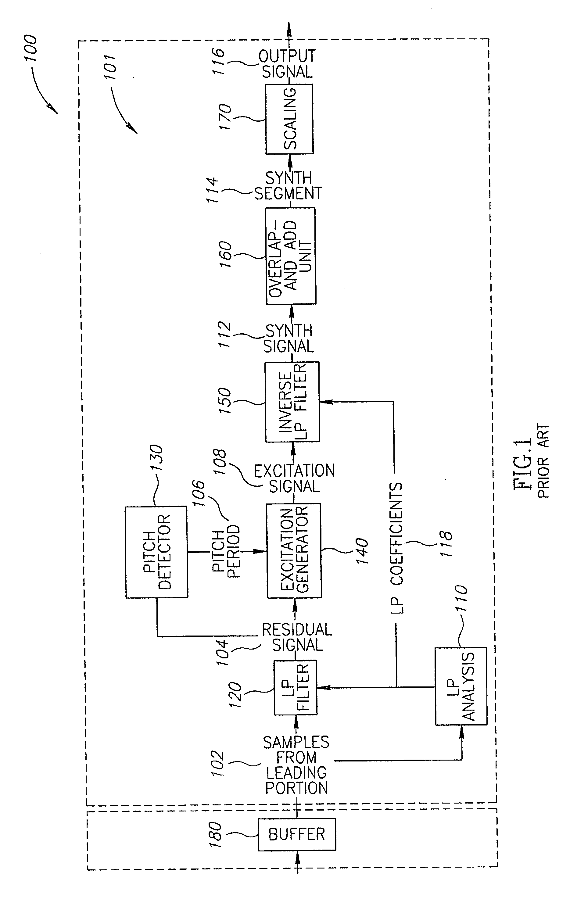
[0032]Reference is made to FIG. 1, which schematically shows an exemplary functional block diagram of a linear prediction (LP) based packet loss concealment (PLC) module 101 known in the art comprised in a receiver 100. PLC module 101 uses a linear prediction technique to synthesize an audio waveform segment optionally based on a leading portion of the audio waveform. Incoming packets to the receiver are processed such that a last received packet is temporarily stored in a buffer for possible use in PLC applications should an immediately following packet not arrive.

[0033]In a typical PLC application a leading portion 102 associated with the last received packet, or a plurality of last received packets, stored in a buffer 180, is input to LP filter 120. LP filter 120 comprises a finite impulse response (FIR) filter with frequency response characteristics determined by LP coefficients 118, which are generated by a LP analysis circuitry 110. Responsive to the LP coefficients LP filter ...


PUM


Abstract

A method for using a waveform segment in place of a missing portion of an audio waveform generated in response to a packet stream encoding portions of the audio waveform, the method comprising: phase matching a trailing portion of the waveform segment with a trailing portion of the audio waveform that follows the missing portion; and adding the phase matched waveform segment to the audio waveform.

Description

FIELD[0001]The invention relates to audio transmission over packet switched networks.BACKGROUND[0002]A packet switched network is a communication network that transmits data from a sender to a receiver packaged in packets, which are routed from the sender to the receiver over a network of switching nodes connected by “data links”. Each switching node receives packets via links that connect it to other switching nodes and switches packets that it receives to forward them over other data links that are suitable for bringing the packets to their destinations. Any two given packets may propagate over different routes, i e. different configurations of nodes and links, from a same sender to a same receiver. Examples of such packet switched networks are Arpanet, which was established more than thirty years ago and is the first packet switched network, and the Internet. The Internet is used today for all types of data communication and is commonly used to transmit multimedia data and for vo...

Claims


Application Information

Patent Timeline
IPC IPC(8): G10L19/04
CPCG10L19/005
Inventor RAIFEL, MARKSHTERLICH, GUYCHEN, YAKOV
Owner AUDIOCODES LTD
Why Eureka
Try Eureka