IC card with low precision clock

a low-precision, clock technology, applied in the field ofic cards, to avoid power consumption

Active Publication Date: 2008-11-27
STMICROELECTRONICS INT NV
View PDF25 Cites 189 Cited by
  • Summary
  • Abstract
  • Description
  • Claims
  • Application Information

AI Technical Summary

Benefits of technology

[0020]The problem that serves the basis of the embodiments is to provide an IC Card for measuring time independently with respect to the reader device whereto the IC Card is connected. This allows the IC Card to be aware of time, not only when the reader device suspends the clock signal for avoiding power consumption, but also to be able to measure time independently with respect to potentially not trusted host devices, not always available and not precise in providing a timer service. Such an IC Card also avoids a maximum power consumption for an internal clock during the clock stop status, thus overcoming the limitations of the current IC Card in measuring time over multiple APDUs, during security operations, as well as overcoming other limitations that currently affect the known IC Cards.

Problems solved by technology

The problem that serves the basis of the embodiments is to provide an IC Card for measuring time independently with respect to the reader device whereto the IC Card is connected.

Method used


Image

  • IC card with low precision clock
  • IC card with low precision clock
  • IC card with low precision clock

Examples


Embodiment Construction

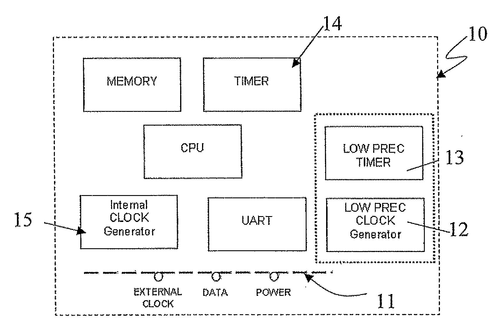
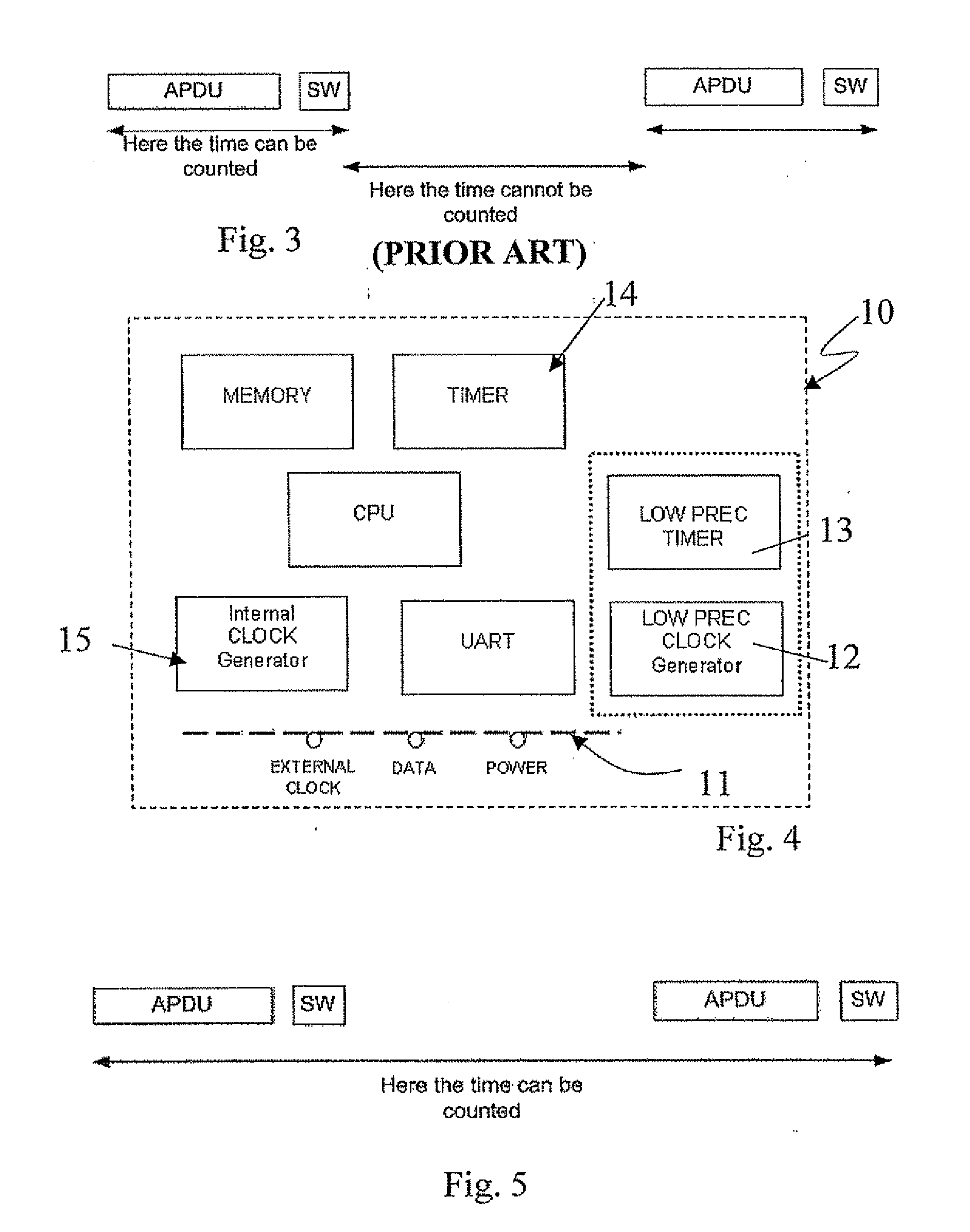
[0031]With reference to the annexed drawings and in particular with reference to FIG. 4, it is schematically represented and globally referenced with 10 an IC Card comprising electronic components, such as a memory portion, a timer, a CPU and a UART.

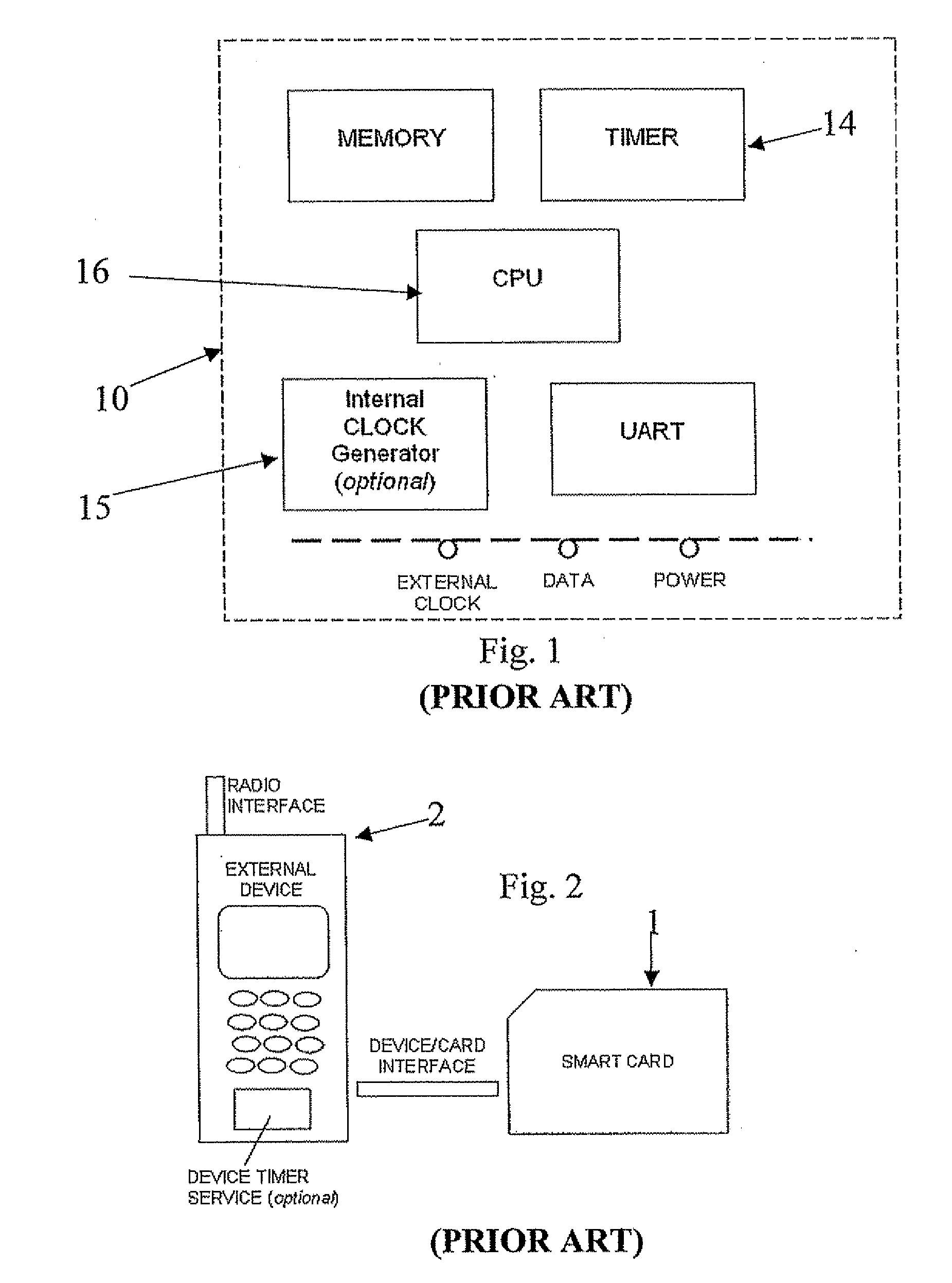
[0032]The IC Card 10 may be connected via a bus 11 to a reader device, not represented because it is conventional. When connected, the reader device provides a power supply to the IC Card 10, and a clock signal for synchronizing electronic components inside the IC Card 10, for example, for synchronizing the instruction decoder, the ALU, and the memory bus. The above clock signal will be referred hereinafter as the main clock signal.

[0033]To save energy, the reader device may enter in a main clock stop status wherein it suspends the main clock signal. The IC Card 10 reacts by suspending the power supply to one or more electronic components used for counting time, like the timer, and the CPU, for example.

[0034]The IC Card 10 may also compr...


PUM


Abstract

An IC Card may include electronic components to receive a power supply and a main clock signal by a reader device. The power supply may be provided to a subset of the electronic components during a main clock stop status wherein the main clock signal is suspended for avoiding a maximum power consumption threshold. The IC Card may also include a low precision clock included in the subset of electronic components for measuring time in the main clock stop status.

Description

FIELD OF THE INVENTION[0001]The present invention relates to IC Cards, and, more particularly, to IC Card clocks.BACKGROUND OF THE INVENTION[0002]As it is well known, an IC Card is an electronic device intended to communicate with a reader device via a standard communication channel, generally comprising a contact pad of the IC Card. As schematically represented in FIG. 1, the IC Card comprises electronic components, for example, a CPU and one or more memory portions for storing data, and the IC Card is generally powered by the reader device, for example, through a contact between the contact pad of the IC Card and a respective contact pad on the reader device. More particularly, the reader device is responsible not only to power the CPU and the memory portions of the IC Card, but also to provide a clock signal to the IC Card for the synchronization of the electronic components of the IC Card.[0003]The reader device includes a clock for generating, by an oscillator, a stationary and...

Claims


Application Information

Patent Timeline
Patent Type & Authority Applications(United States)
IPC IPC(8): G06F1/04
CPCG06F1/14
Inventor VARONE, FRANCESCOVASTANO, PASQUALEVENEROSO, AMEDEO
Owner STMICROELECTRONICS INT NV
Why Eureka
Try Eureka