Central auger crop feed system for a harvester

Inactive Publication Date: 2008-12-04
CLAAS SELBSTFAHRENDE ERNTEMASCHINEN GMBH
View PDF30 Cites 31 Cited by
  • Summary
  • Abstract
  • Description
  • Claims
  • Application Information

AI Technical Summary

Benefits of technology

[0008]The present invention is an improved crop feed path in a belt header into a combine or harvester feeder house. It is determined, surprisingly, that removin

Problems solved by technology

This ninety degree turn could lead to disadvantageous misaligments and interruption of flow of long stalk crops as they were fed into the feeder house.
This crop falling onto the center belt simultaneously with the center belt receiving opposing crop feeds from the lateral belts cause

Method used


Image

  • Central auger crop feed system for a harvester
  • Central auger crop feed system for a harvester
  • Central auger crop feed system for a harvester

Examples


Embodiment Construction

[0026]The following description of the preferred embodiment(s) is merely exemplary in nature and is in no way intended to limit the invention, its application, or uses.

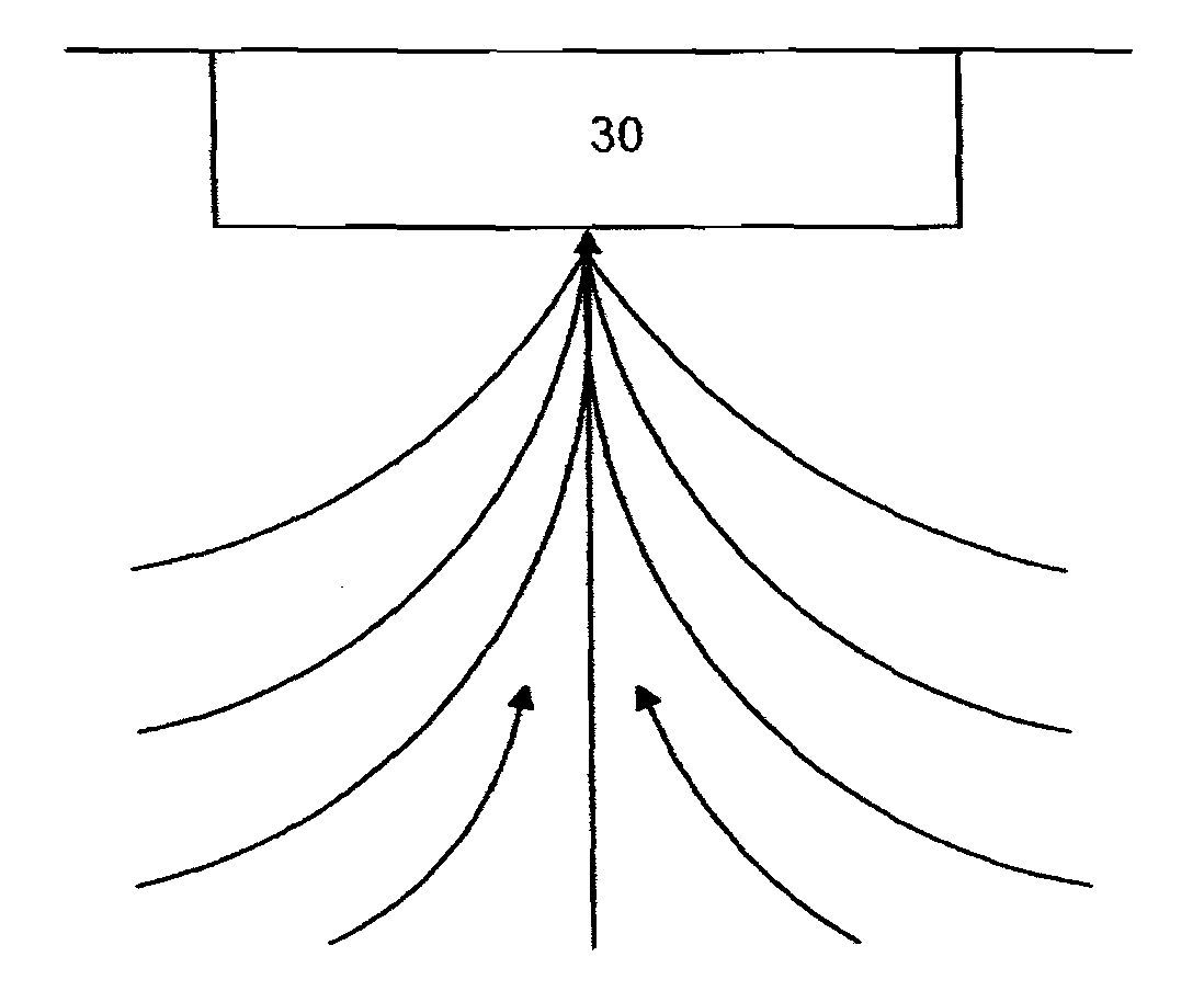
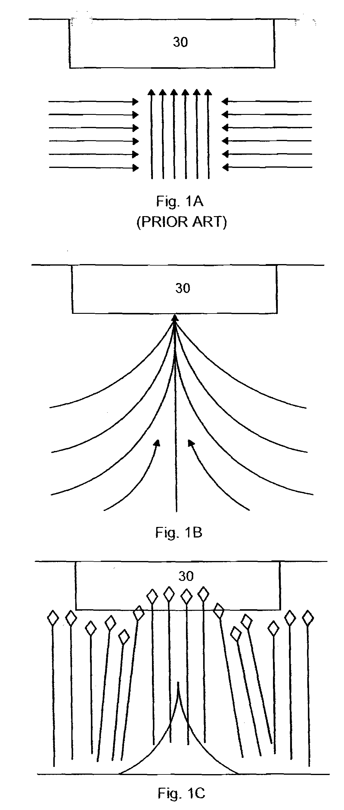
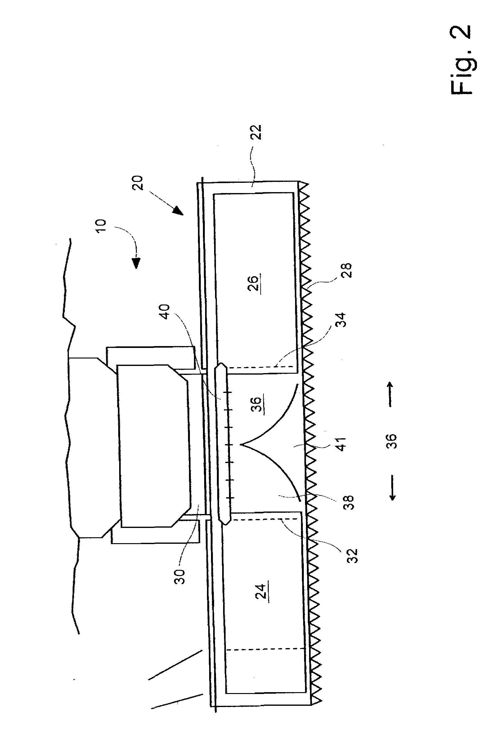
[0027]Referring now to the drawings in which like reference numbers correspond to like elements, FIG. 2 is a schematic top view of a combine or harvester 10 having a header 20. Generally, the header is comprised of a frame 22 supporting two opposing crop conveying belts 24 and 26, sometimes known to those of skill in the art as “drapers.” The leading edge of the header 20 includes a cutter bar 28. A reel disposed over the cutter bar and the leading edge of the belts 24 and 26 is omitted for clarity. The object of feeder systems is to direct crop cut by the cutter bar 28 into a conventional opening in the front of a feeder house 30, through which cut crop travels rearwards to be further threshed and processed within the combine or harvester. In the depicted embodiment, the header is fixedly attached to a feeder house

[0...


PUM


Abstract

A header for a combine or harvester has a frame with a longitudinal dimension transverse to a direction of travel of the combine or harvester. Two moving belts are disposed on the frame to receive cut crop from a cutter and to move the crop from outer portions of the header towards an inner portion of the header. Each of the belts has a leading edge oriented towards the direction of travel of the combine or harvester and a trailing edge oriented away from the direction of travel and each of the belts has an inner aspect disclosed in spaced relation to an inner aspect of the other of the belts such as to define a gap therebetween, the gap receiving cut crop being transported longitudinally and inwardly from the belts. An auger with a cylinder and two end cones around an axis is disposed to urge crop from the gap and from the inner aspect of the belts towards a feeder house position behind the gap. The axis of the auger is forward of the trailing edge of the belt. A stationary floor plate beneath the gap is contoured to urge crop into the feeder house.

Description

BACKGROUND OF THE INVENTION[0001]1. Field of the Invention[0002]The present invention is in the field of headers for combines and harvesters, particularly “draper” headers.[0003]2. Related Art[0004]Combines and harvesters having headers with conveyor belts, often called “drapers,” are known in the art. The belts convey cut crop from the outer ends of the header towards the center of the header for feeding into the combine feeder house. In a typical prior art header, two lateral conveyor belts whose longitudinal dimension would be perpendicular to the direction of travel of the combine, transport crops to the center of the header by rotating their top surface from the outside in. Then a third belt with a direction of rotation parallel to the direction of travel of the vehicle, was disposed between and underneath the inside ends of the lateral belts. This belt would catch the crop from both lateral belts and transport it back into the feeder house, usually with the help of an auger di...

Claims


Application Information

Patent Timeline
IPC IPC(8): A01D43/06A01D45/02A01D57/26A01F17/02
CPCA01D57/20
Inventor TIPPERY, STEVEKASTER, CRAIGHAWORTH, ADAM LEENATHAN, CRISTOPHPETERSEN, JENS O.
Owner CLAAS SELBSTFAHRENDE ERNTEMASCHINEN GMBH
Why Eureka
Try Eureka