
Electronic apparatus

a technology of electronic equipment and e-mail, which is applied in the field of electronic equipment, can solve the problems of delay in the inflow of liquid into the inner space of the enclosure, and achieve the effect of preventing collisions and reliably preventing damages

Inactive Publication Date: 2008-12-04
FUJITSU CLIENT COMPUTING LTD
View PDF8 Cites 31 Cited by
  • Summary
  • Abstract
  • Description
  • Claims
  • Application Information

AI Technical Summary

Benefits of technology

[0006]It is accordingly an object of the present invention to provide an electronic apparatus enabling delay of inflow of liquid into the inner space of an enclosure.
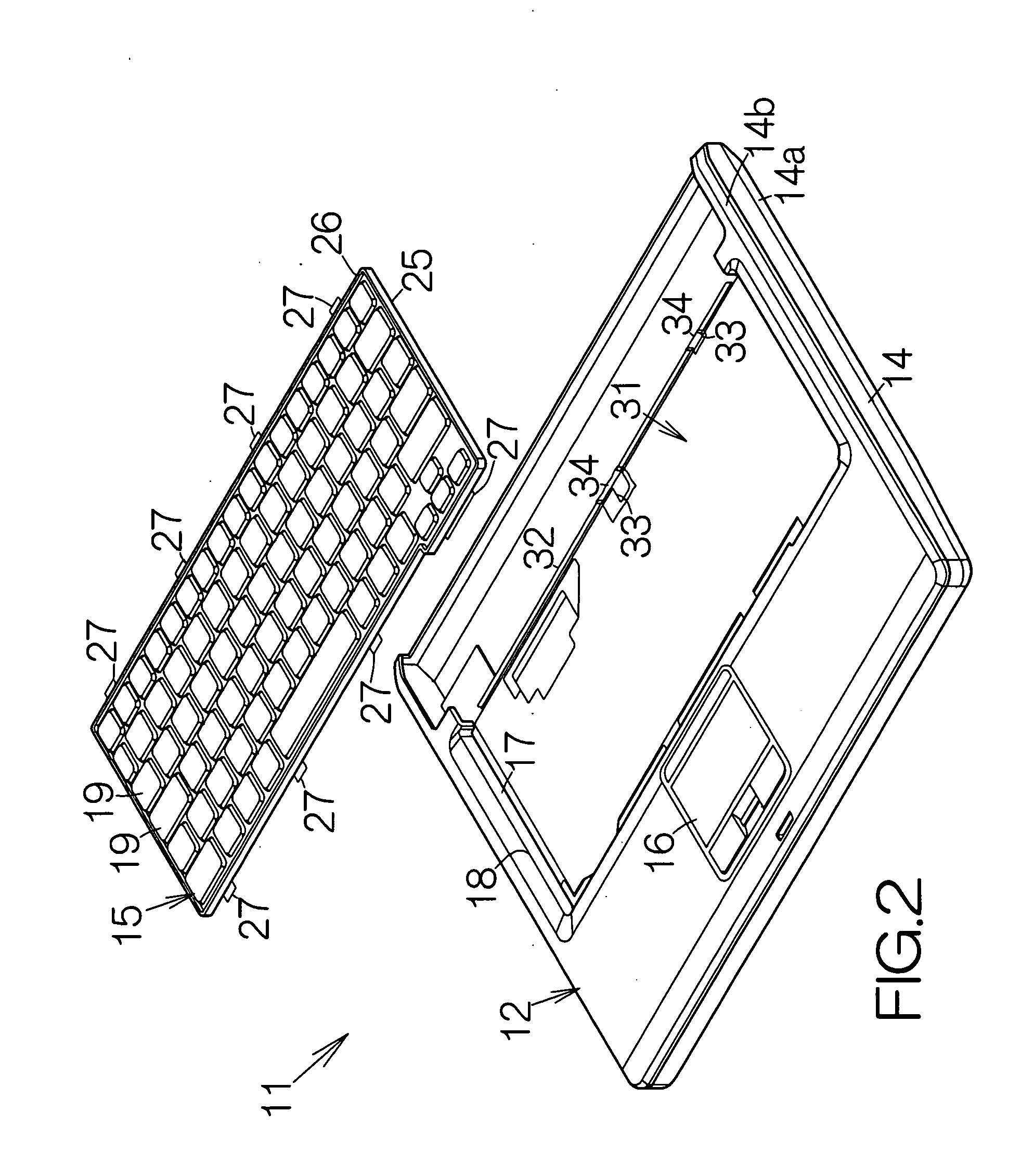
[0008]When liquid such as coffee is spilled on the keyboard during a user's operation on the electronic apparatus, for example, the liquid flows into a space between the keyboard and the window opening. The keyboard and the edge of the enclosure are received on the support member. Even if there is a gap between the edge and the support member, the surface tension of the liquid serves to prevent the liquid from immediately leaking outside the window opening through the gap between the edge and the support member. The liquid then starts gradually leaking outside the window opening, or leaking into the inner space of the enclosure, through the gap between the edge and the support member. The wall of the support member blocks the liquid. The liquid is gradually accumulated in a space between the edge and the wall. It thus takes a while before the liquid flows over the wall. This results in delay of inflow of the liquid into the inner space of the enclosure. The user can save data prior to inflow of the liquid, for example. The data can be prevented from being lost.
[0010]The electronic apparatus allows preventing the keypads from immersion of the liquid with the assistance of the waterproof support plate, for example. The liquid on the surface of the waterproof support plate spills out of the outer periphery of the waterproof support plate. The surrounding wall stands upright from the outer periphery of the waterproof support plate. The surrounding wall thus blocks the liquid. The liquid flowing over the surrounding wall is accumulated in a gap between the surrounding wall and the window opening. The surface tension of the liquid serves to prevent the liquid from immediately flowing outside the window opening, or flowing into the inner space of the enclosure, through the gap between the edge and the support member. Likewise, the liquid is accumulated in a space between the edge and the wall. It thus takes a while before the liquid flows over the wall. The liquid is prevented from immediately flowing from the keyboard into the enclosure in the electronic apparatus. Here, the edge of the enclosure may be placed at a position between the wall of the support member and the surrounding wall of the waterproof support plate.
[0012]The support member or heat radiating plate allows efficient radiation of the heat of the heat generating component. The heat generating component is prevented from a rise in the temperature. The heat generating component is thus prevented from receiving any damages. The support member, enabling prevention of inflow of the liquid into the inner space of the enclosure, also serves to radiate the heat of the heat generating component. This results in a reduction in the number of components in the electronic apparatus. The production cost of the electronic apparatus is thus suppressed. The electronic apparatus is also allowed to enjoy a reduced weight. The electronic apparatus is also allowed to enjoy a simplified structure. The electronic apparatus can thus be made in a relatively facilitated manner.
[0013]The electronic apparatus may further comprise a detection circuit designed to detect liquid inside the window opening. When liquid is spilled on the keyboard of the electronic apparatus, the liquid flows into a space between the keyboard and the window opening. The detection circuit detects the inflow of the liquid inside the window opening. The detection of the liquid is notified to a user, for example. The user can save data prior to inflow of the liquid into the inner space of the enclosure, for example. The data can be prevented from being lost.
[0015]The electronic apparatus may further comprise a hard disk drive. The aforementioned controller circuit may establish a predetermined silent state of the hard disk drive when the detection circuit detects liquid. When the silent state is established in the hard disk drive, a head slider may be positioned at a predetermined unload position, for example. A so-called ramp member may be employed to hold the head slider outside a magnetic recording disk, for example. The head slider is in this manner reliably prevented from collision against the magnetic recording disk. Even if the supply of power stops, the hard disk drive is reliably prevented from receiving damages. In the case where the supply of power accidentally stops during the operation of the hard disk drive, for example, the magnetic recording disk stops rotating while the flying head slider flies above the magnetic recording disk. The head slider thus inevitably collides against the surface of the magnetic recording disk. The hard disk drive is damaged.

Problems solved by technology

This results in delay of inflow of the liquid into the inner space of the enclosure.

Method used


Image

  • Electronic apparatus
  • Electronic apparatus
  • Electronic apparatus

Examples


Embodiment Construction

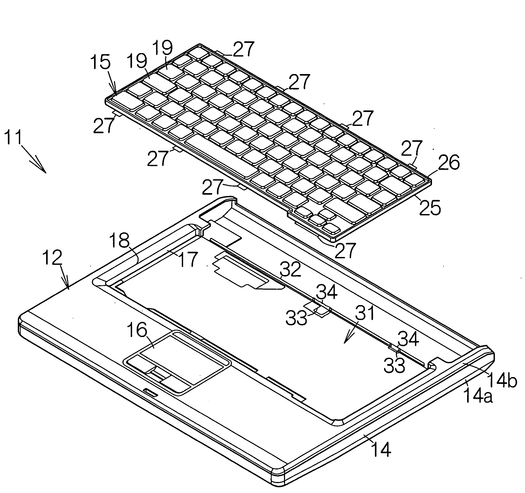
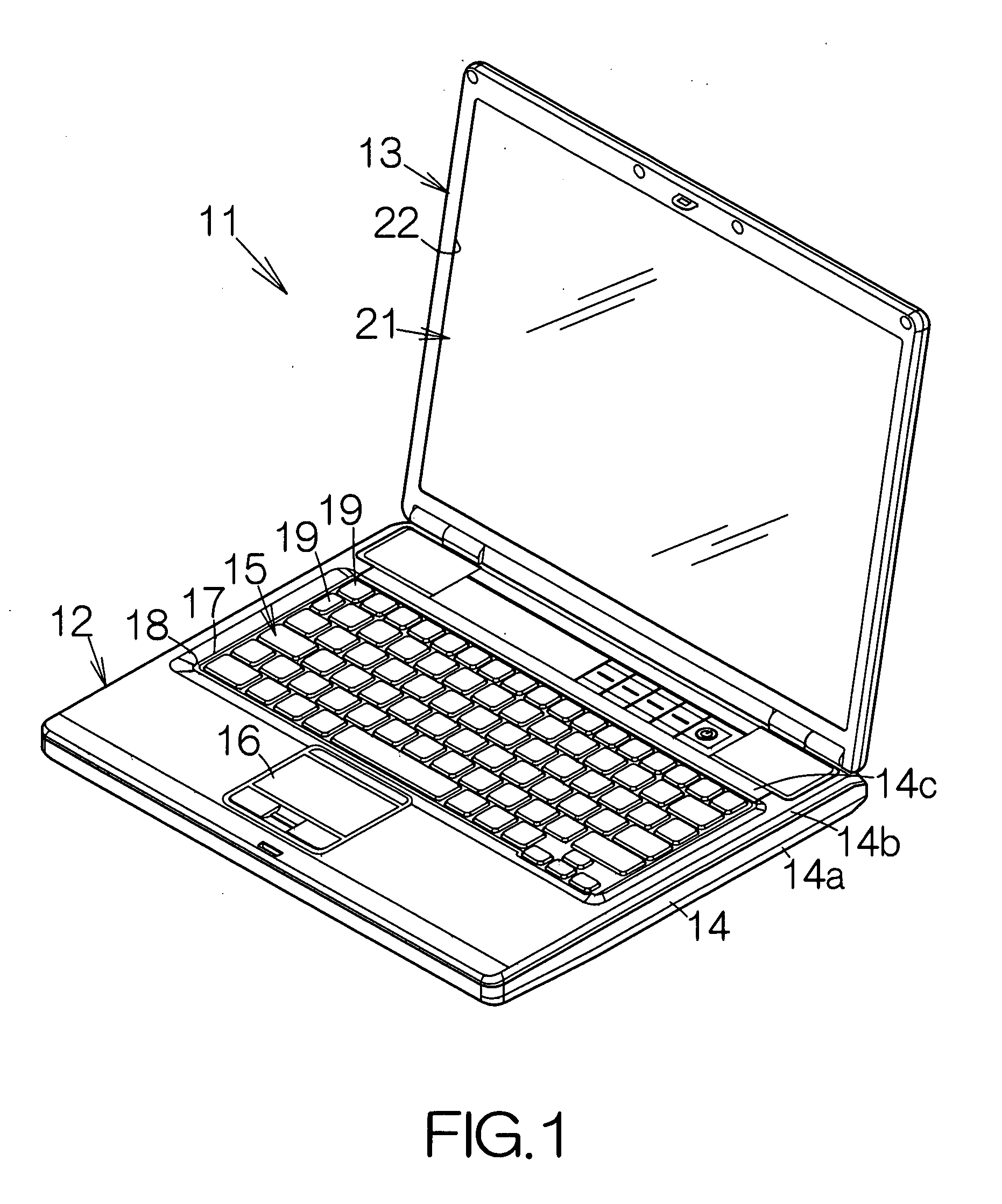
[0024]FIG. 1 schematically illustrates a notebook personal computer 11 as a specific example of an electronic apparatus according to the present invention. The notebook personal computer 11 includes a thin main body 12 and a display enclosure 13. The display enclosure 13 is coupled to the main body 12 for relative swinging or pivotal movement. The display enclosure 13 can be superposed on the main body 12 through the pivotal movement relative to the main body 12.

[0025]The main body 12 includes an enclosure 14. The enclosure 14 may be made of a resin material such as polycarbonate, for example. A molding process may be employed to form the enclosure 14, for example. The enclosure 14 includes a base 14a, a front cover 14b and a rear cover 14c. The front cover 14b is removably coupled to the base 14a. The rear cover 14c is likewise removably coupled to the base 14a. The front cover 14b and the rear cover 14c in combination define the front surface of the enclosure 14 thereon. The front...


PUM


Abstract

An enclosure has an edge for defining a window opening. A keyboard is set in the window opening. A support member attached to the enclosure from the inside of the enclosure to receive the edge of the enclosure and the keyboard. A wall stands upright from the surface of the support member at a position outside the window opening. When coffee is spilled on the keyboard, the liquid flows into a space between the keyboard and the window opening. The surface tension of the liquid serves to prevent the liquid from immediately leaking outside the window opening through the gap between the edge and the support member. The liquid then starts leaking outside the window opening through the gap. The wall of the support member blocks the liquid. It thus takes a while before the liquid flows over the wall.

Description

BACKGROUND OF THE INVENTION[0001]1. Field of the Invention[0002]The present invention relates to an electronic apparatus including: an enclosure having a window opening; and a keyboard set in the window opening.[0003]2. Description of the Prior Art[0004]A notebook personal computer includes a keyboard. The keyboard is set in a window opening defined in the front surface of the enclosure as disclosed in Japanese Patent Application Publication No. 2002-352659, for example. The keyboard includes a support plate supporting keypads. A surrounding wall stands upright from the surface of the support plate along the outer periphery of the support plate. When liquid is spilled on the keyboard, for example, the liquid is blocked by the surrounding wall. The liquid is in this manner prevented from flowing into the inner space of the enclosure through a gap between the keyboard and the edge of the window opening.[0005]However, when a user spills coffee, for example, on the keyboard during the u...

Claims


Application Information

Patent Timeline
Patent Type & Authority Applications(United States)
IPC IPC(8): G06F1/16
CPCG06F1/1616G06F1/1656G06F1/1662
Inventor HATTORI, MASAHIKOOHNISHI, MASUOAOYAMA, YUJI
Owner FUJITSU CLIENT COMPUTING LTD
Learn More