Contactless power transferring coil unit, mobile terminal, power transmitting apparatus, and contactless power transferring system

a technology of contactless power transfer and coil unit, which is applied in the direction of power management, instruments, transportation and packaging, etc., can solve the problems of insufficient charging power for the rechargeable battery of the mobile terminal, the power consumption of the mobile terminal exceeds the power supplied from the cradle, and the efficiency of the contactless power transfer between the coils. , to achieve the effect of suppressing heat generation, reducing leakage magnetic flux, and increasing generated voltag

Active Publication Date: 2008-12-04
SONY ERICSSON MOBILE COMM JAPAN INC +1
View PDF10 Cites 118 Cited by
  • Summary
  • Abstract
  • Description
  • Claims
  • Application Information

AI Technical Summary

Benefits of technology

[0016]In other words, when the center positions of the primary-side and secondary-side contactless power transferring coils are displaced, leaking magnetic flux will be generated by at least the secondary-side contactless power transferring coil. According to embodiments of the invention, the displacement between the center positions of the coils can be detected by detecting such leaking magnetic flux using a leaking flux detecting coil. Also, in the power transmitting apparatus according to the embodiment of the invention, it is possible to know, based on the output of the leaking flux detecting coil on the secondary side, that a displacement has occurred between the center positions of the coils. In that case, the transfer of power from the primary-side contactless power transferring coil is controlled so that a larger generated voltage is obtained by the secondary-side contactless power transferring coil unit and the leaking magnetic flux is reduced.
[0017]According to embodiments of the invention, when a displacement has occurred between the center positions of the primary and secondary-side contactless power transferring coils, the leaking magnetic flux th...

Problems solved by technology

However, when contactless power transfer is carried out in a state where the primary transfer coil on the power transmitting side and the secondary transfer coil on the power transmitting side are disposed facing one another, if the center positions of the primary transfer coil and the secondary transfer coil are displaced, for example, there may be a fall in the efficiency of the contactless power transfer between the coils.
This means that when contactless power transfer is carried out between a primary transfer coil provided in a cradle and a secondary transfer coil provided in a mobile terminal, for example, to charge secondary cells of the mobile terminal, in a case where the center positions of both coils are displaced so that the power transferring efficiency falls and the power consumption of the mobile terminal exceeds the power supplied from the cradle, the charging power will be insufficient to charge the rechargeable battery of the mobile terminal.
Here, if more power is transferred from the cradle to compensate for the charging power being insufficient, ...

Method used


Image

  • Contactless power transferring coil unit, mobile terminal, power transmitting apparatus, and contactless power transferring system
  • Contactless power transferring coil unit, mobile terminal, power transmitting apparatus, and contactless power transferring system
  • Contactless power transferring coil unit, mobile terminal, power transmitting apparatus, and contactless power transferring system

Examples


Embodiment Construction

[0050]Preferred embodiments of the invention will now be described with reference to the attached drawings.

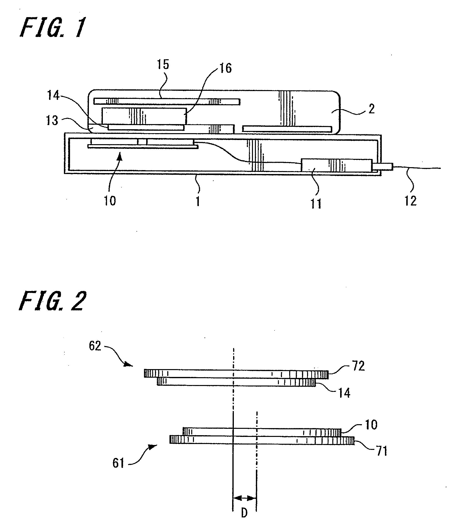
[0051]In the embodiment, an example of a flat coil formed by winding a conductive wire, such as a solid wire, a twisted wire, or a flat pattern, into a spiral on a substantially flat plane is described as a “contactless power transferring coil” according to an embodiment of the invention. Further, a mobile-phone unit including the flat coil described above as a secondary coil for contactless power transfer is described as one example of a “mobile terminal” according to an embodiment of the invention. Furthermore, a cradle that is capable of charging at least the mobile-phone unit described above and includes the flat coil described above as a primary coil for contactless power transfer is described as one example of a “power transmitting apparatus” according to an embodiment of the invention. Moreover, a system including such mobile-phone unit and cradle is described as one exa...


PUM


Abstract

A contactless power transferring coil unit is provided. The contactless power transferring coil unit includes a flat coil, a magnetic film, and a leaking flux detecting coil. The flat coil is formed by winding a conductive wire into a spiral on a substantially flat plane. The magnetic film is disposed so as to cover one entire flat surface of the flat coil. The leaking flux detecting coil is disposed in a periphery outside an outer edge of the flat coil and the magnetic film and detects leaking magnetic flux from the flat coil.

Description

CROSS REFERENCES TO RELATED APPLICATIONS[0001]The present invention contains subject matter related to Japanese Patent Application JP 2007-140893 filed in the Japanese Patent Office on May 28, 2007, the entire contents of which being incorporated herein by reference.BACKGROUND OF THE INVENTION[0002]1. Field of the Invention[0003]The invention relates to a contactless power transferring coil unit for transferring power by a contactless method using electromagnetic induction such as when charging secondary cells incorporated in a small and slim mobile terminal (for example, a mobile-phone unit). The invention further relates to a mobile terminal in which the contactless power transferring coil unit is incorporated, a power transmitting apparatus that transfers power to a mobile terminal or the like using a contactless power transferring coil, and a contactless power transferring system including such devices.[0004]2. Description of the Related Art[0005]An existing system is known for ...

Claims


Application Information

Patent Timeline
IPC IPC(8): H01F27/28H02J7/00H04M1/00H04W52/00
CPCH01F27/2871H02J7/025H01F38/14H02J50/10H02J7/00045H02J50/005H02J50/90H02J50/70H02J50/12
Inventor KATO, HIROSHISUZUKI, KUNIHARUSUZUKI, KATSUYAYAMAZAKI, MANABUONISHI, KOTAYODA, KENTAROKONDO, YOICHIROJIN, MIKIMOTOKAMIJO, TAKAHIROSOGABE, HARUHIKO
Owner SONY ERICSSON MOBILE COMM JAPAN INC
Why Eureka
Try Eureka