Method and System for Digital Triggering for an Oscilloscope
- Summary
- Abstract
- Description
- Claims
- Application Information
AI Technical Summary
Benefits of technology
Problems solved by technology
Method used
Image

Examples
first embodiment
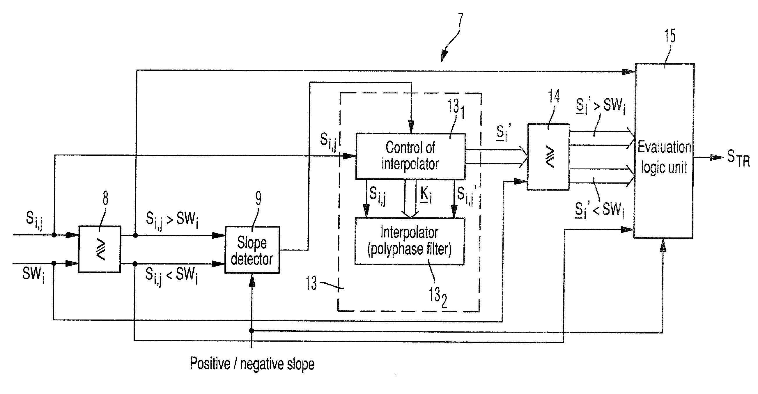
[0046]In a first iterative step, by analogy with the first embodiment, by means of interpolation in a polyphase filter within the unit 13′ for determining additional sampled values Si′ of the reference signal Si, the additional sampled value Si,j′ of the reference signal Si is determined in the middle of the time interval, which is defined by the two sampled values Si,j and Si,j−1 of the reference signal Si disposed respectively before and after the identified slope event. In all subsequent iterative steps j, the unit 13 for determining additional sampled values Si′ of the reference signal Si determines the additional sampled value Si,j′ of the reference signal Si in the middle of the time interval, which is established by the additional sampled value Si,j−1′ of the reference signal Si determined in the preceding iterative step j−1 and the time-interval threshold determined in the preceding iterative step j−1, which is disposed in the direction of the threshold value SWi relative to...
third embodiment
[0059]In the preceding trigger-combining logic unit 29, several signals S1, S2, . . . , SN from several signals S to be displayed on the digital oscilloscope are combined in an arithmetic and / or logical manner with their reference signal Si. The reference signal Si and two or more other signals SM+1, SM+2, . . . acting as reference signals from several signals S to be presented on the digital oscilloscope are compared in each case in a first, second or third embodiment of the digital unit for generating triggering signals 7i, 7i′, 7i″, 7M+1, 7M+1′, 7M+1″, 7M+2, 7M+2′, 7M+2″, . . . respectively with reference to overshooting or undershooting an identical threshold value SWi. The triggering signals STR1, STRM+1, STRM+2, . . . activated at the respectively determined triggering time are combined with one another in an arithmetic and / or logical manner in a subsequent unit for combining triggering signals 29′ to form a combined triggering signal STR.
[0060]In a fourth embodiment 5′″ of th...
second embodiment
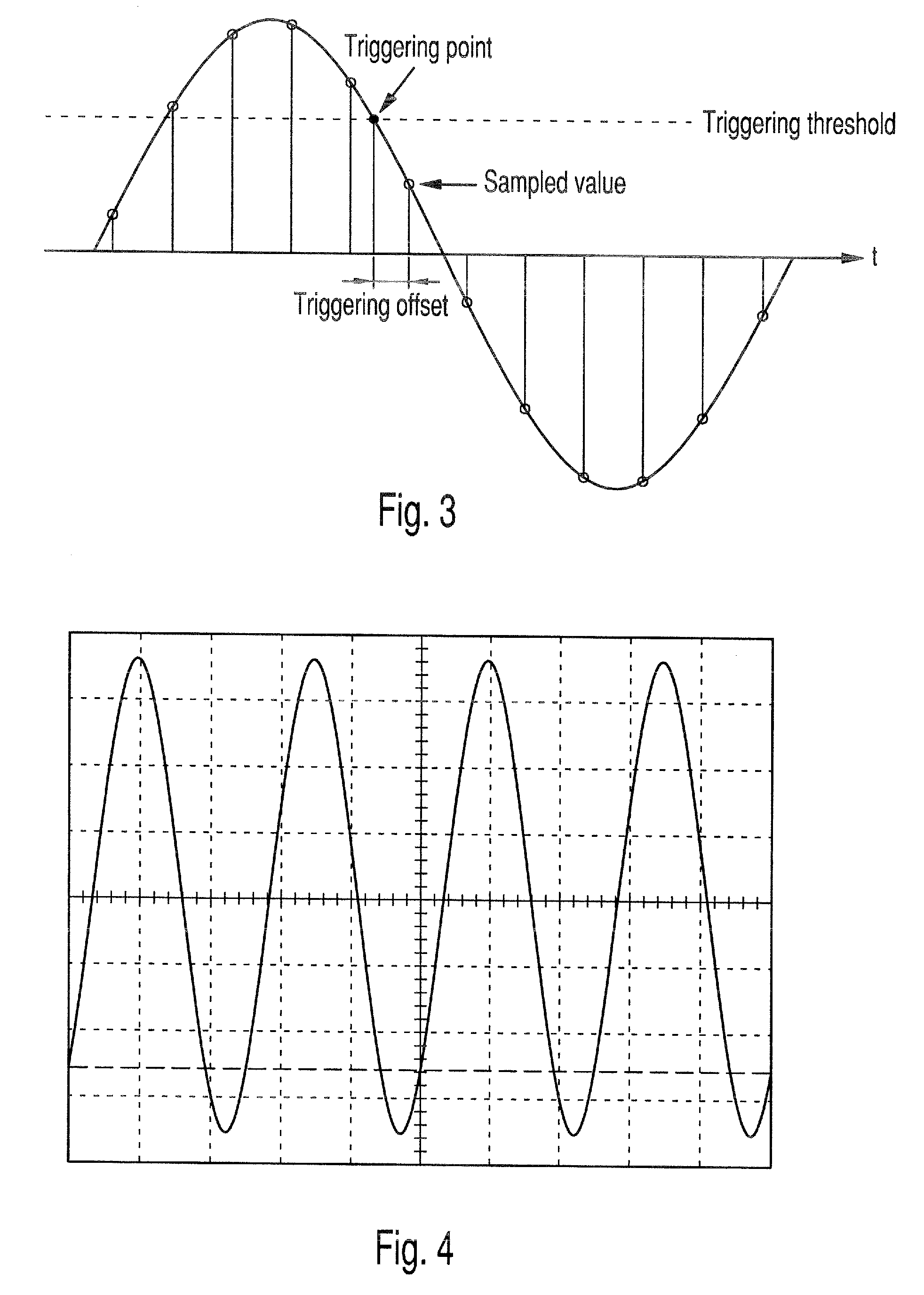
[0077]With the example of a sinusoidal signal and a specified threshold value, FIG. 11B shows how, in the method for generating triggering signals, the additional sampled value Si,j′ of the reference signal Si, which provides the minimum difference relative to the threshold value, is determined as the triggering time of the triggering signal by an iterative determination of additional sampled values Si,1, Si,2 and Si,3.
[0078]The third embodiment of the method for generating triggering signals shown in FIG. 6C, which expands the second embodiment of the method for generating triggering signals as shown in FIG. 6B, contains the procedural stages S100, S110, S120, S130, S140, S150 and S160 of the second embodiment of the method for generating triggering signals within its procedural stages S200, S210, S220, S230, S240, S250 and S260.
[0079]In the final procedural stage S270, on the basis of the additional sampled values Si,j′ and Si,j−1′ of the reference signal Si determined in the last...
PUM
 Abstract
Description
Claims
Application Information
 - Generate Ideas
- Intellectual Property
- Life Sciences
- Materials
- Tech Scout
- Unparalleled Data Quality
- Higher Quality Content
- 60% Fewer Hallucinations
Browse by: Latest US Patents, China's latest patents, Technical Efficacy Thesaurus, Application Domain, Technology Topic, Popular Technical Reports.
© 2025 PatSnap. All rights reserved.Legal|Privacy policy|Modern Slavery Act Transparency Statement|Sitemap|About US| Contact US: help@patsnap.com