Ink jet printing apparatus and ink jet printing method

a printing apparatus and ink jet technology, applied in the field of printing apparatuses, can solve the problems of non-ejection, degrading image quality or damage to the print head, accumulated heat to be accumulated in the print head, etc., and achieve the effect of increasing the temperature of the print head and reducing the possibility of density or hue unevenness

Active Publication Date: 2008-12-04
CANON KK
View PDF4 Cites 4 Cited by
  • Summary
  • Abstract
  • Description
  • Claims
  • Application Information

AI Technical Summary

Benefits of technology

[0018]The present invention is made in view of the above-described problems. That is, an object of the present invention is to provide an ink jet printing apparatus that can reduce possible density or hue unevenness caused by an increase in the temperature of a print head without the need for a complicated structure or complicated control, as well as a relevant ink jet printing method.
[0022]According to the present invention, even with an increase in the temperature of the print head during printing, the standby time is distributively set for each of the plurality of the scans to be subsequently started. This prevents significant hue or density unevenness from occurring between areas that are completed by a plurality of scans and printed during the respective print scans.

Problems solved by technology

However, since the print head having the plurality of densely arranged print elements allows the electrothermal converting elements provided in the respective print elements to rapidly generate heat and thus energy for ejection, repeated ejections cause heat to be accumulated in the print head.
The accumulated heat may pose a problem.
In the ink jet print head, an excessive increase in temperature may result in non-ejection to degrade image quality or damage the print head.
Such a heat accumulation problem more frequently occurs when an attempt is made to achieve faster printing or to output images of a higher resolution.
However, the method of controlling the driving frequency of the print head as described above can inhibit the print head from increasing excessively but poses a new problem described below.
This disadvantageously increases the costs of the whole apparatus.
However, this method has been found to affect images printed with the standby time set between each print scan and the succeeding print scan.
Specifically, disadvantageously, the density or hue of an area printed with the standby time set between the print scans may be different from that of the other areas.
Consequently, it is difficult to set all the print elements to eject exactly the same amount of ink in exactly the same direction.
Thus, image defects such as stripes and unevenness are visually perceived.
Thus, with the method of varying the standby time between the print scans depending on whether the detected temperature of the print head exceeds the threshold, only the area printed and scanned after the elapse of many standby time periods exhibits a density and a hue that are different from those of the other areas; this is disadvantageously viewed as unevenness.
This problem may occur not only in the case of multicolor printing but also in monochrome printing.
That is, in the case of monochrome printing, density unevenness may occur.
In the case of multicolor printing, density and hue unevenness may occur.

Method used


Image

  • Ink jet printing apparatus and ink jet printing method
  • Ink jet printing apparatus and ink jet printing method
  • Ink jet printing apparatus and ink jet printing method

Examples


first embodiment

[0032]A preferred embodiment of the present invention will be described below in detail with reference to the drawings. In the specification, the term “printing” includes the formation of meaningful information such as characters or figures on a print medium but also the formation of meaningless information on a print medium. The term “print medium” means not only paper, used in common printing apparatuses, but also a material capable of receiving ink, such as a cloth, a plastic film, a metal plate, glass, ceramics, wood, or leather. The term “ink” should be broadly interpreted similarly to the definition of the term “printing”, and means a material applied onto the print medium to form an image, a pattern, or the like.

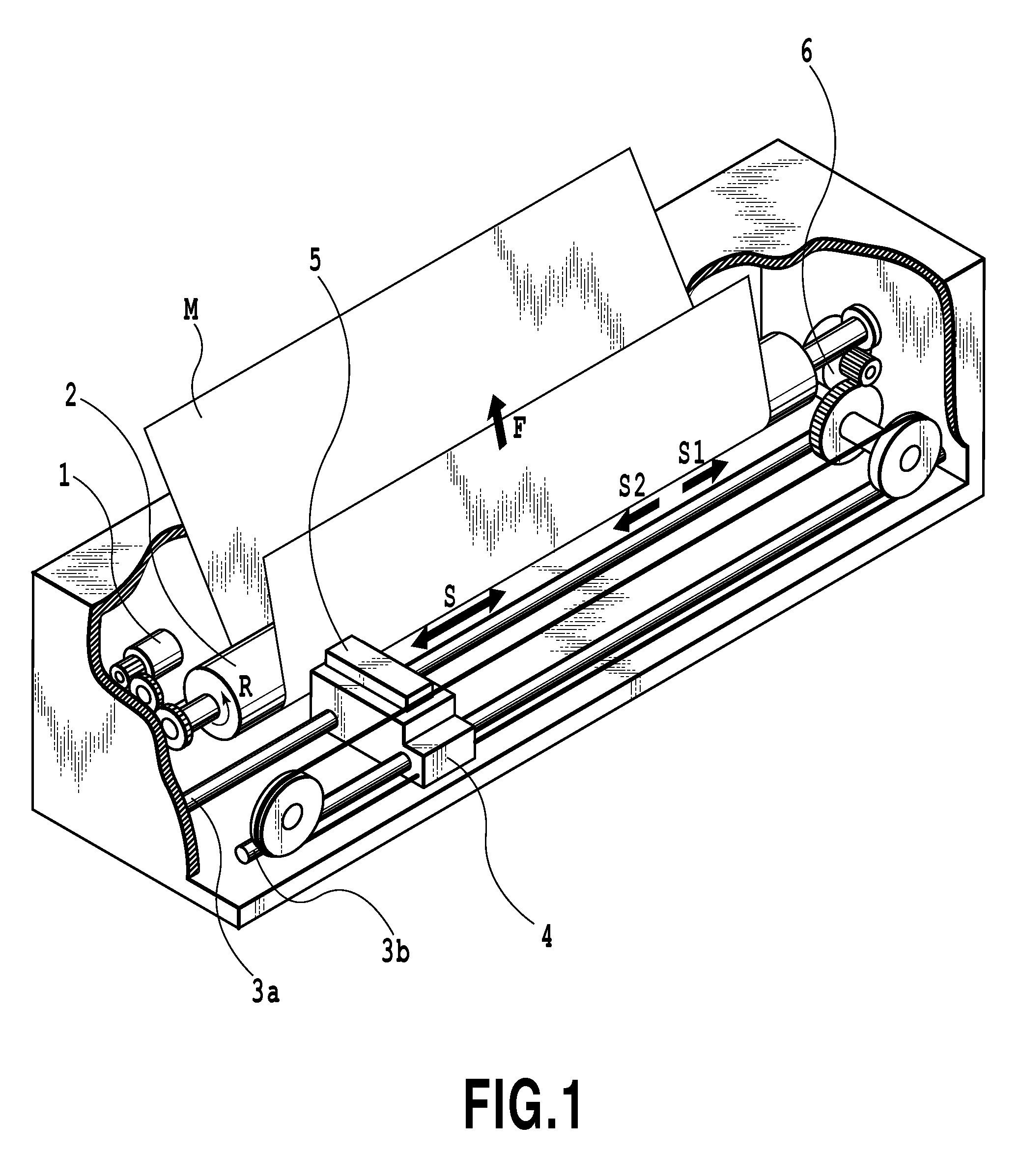
[0033]FIG. 1 is a schematic perspective view illustrating an internal mechanism of an ink jet printing apparatus that is applicable to the present embodiment. In FIG. 1, reference numeral 1 denotes a conveying motor. The conveying motor 1 drivingly rotates a platen ro...

second embodiment

[0056]Now, a second embodiment of the present invention will be described.

[0057]The second embodiment is characterized the standby time set for each scan to be subjected to the standby control is changed according to the head temperature TH and the number n of scans to be subjected to the standby control (scan count) The second embodiment is similar to the first embodiment in the other respects. Consequently, an ink jet printing apparatus according to the second embodiment also has the configuration shown in FIGS. 1 and 2.

[0058]FIG. 6 is a diagram showing a table used to set the standby time in the ink jet printing apparatus according to the present embodiment. The ink jet printing apparatus according to the second embodiment can set the amount of standby time until the start of each scan and the number of scans to be subjected to the standby control (set scan count). For example, if the head temperature is between 66° C. and 70° C. (first level), the scan count is controllably set ...

third embodiment

[0068]Now, a third embodiment of the present invention will be described with reference to FIGS. 7 and 8.

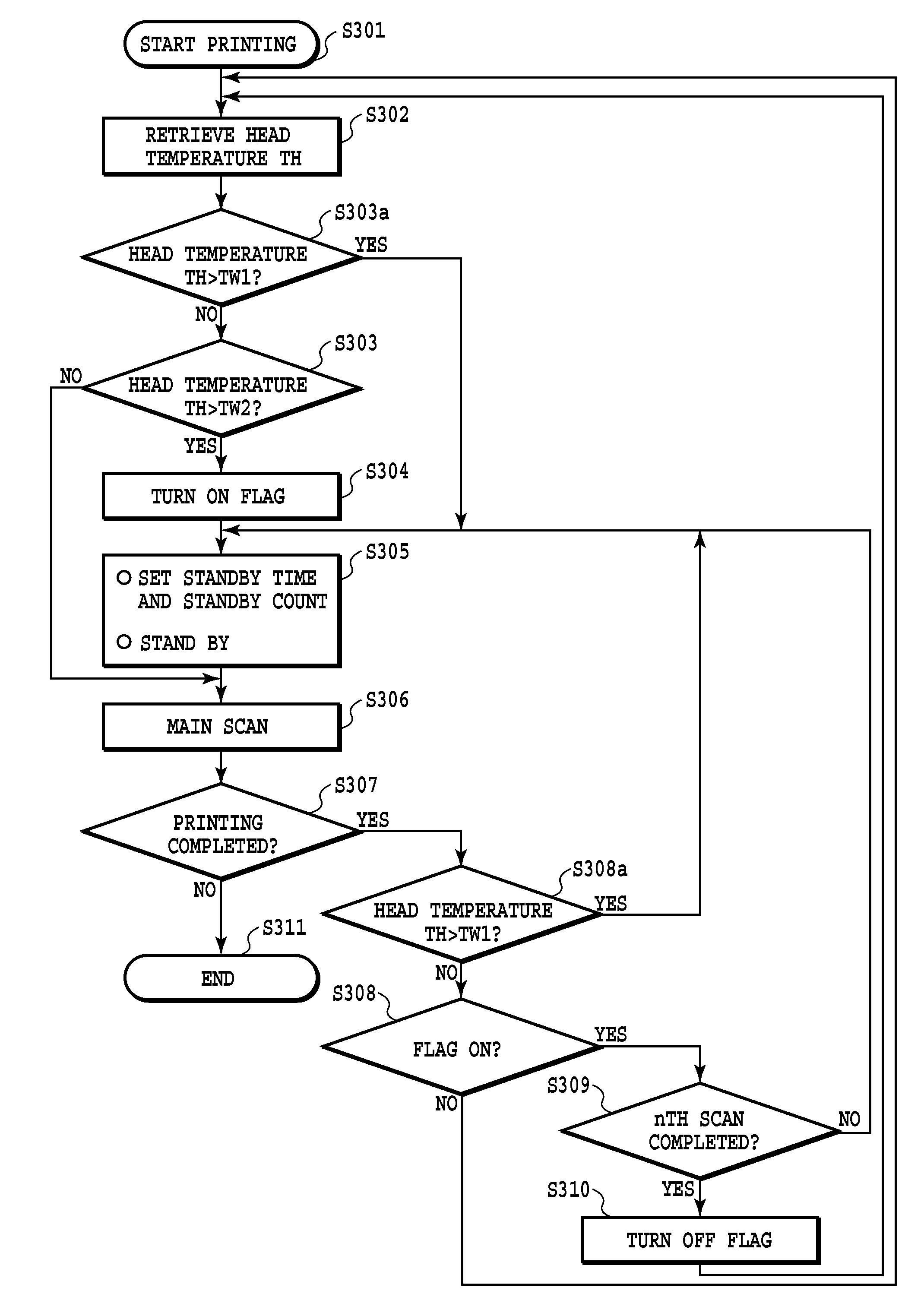
[0069]The head temperature may rapidly become high depending on the structure of the print head or the number of ejections from the print head per unit time. In this case, the head temperature may fail to decrease sufficiently or rise when only the standby control is performed in which a short standby time is set for each of a plurality of scans as in the case of the above-described embodiments. If such a phenomenon occurs, the print head may fail to achieve ejection, significantly degrading the image quality. Thus, in the third embodiment, when the temperature of the print head becomes very high, a long standby time (for example, 1 second) is set for a single print scan to rapidly lower the head temperature TH to avoid possible non-ejection. The ink jet printing apparatus according to the third embodiment also has the configuration shown in FIGS. 1 and 2.

[0070]FIG. 7 is a flowch...


PUM


Abstract

An object of the present invention is to provide an ink jet printing apparatus that inhibits the temperature of a print head from increasing excessively while preventing significant density or hue unevenness from occurring in images, without the need for a complicated structure or complicated control. Thus, the present invention detects temperature of the print head, and sets number of scans in which the print head is to stand by until start of scanning and a standby time for each of the set number of scans by the print head, on the basis of the detected temperature.

Description

BACKGROUND OF THE INVENTION[0001]1. Field of the Invention[0002]The present invention relates to a printing apparatus that ejects ink from a print head to print a print medium, and a relevant printing method, and specifically, to a printing apparatus that controls the temperature of the print head, which is increased by ejection of the ink, and a relevant printing method.[0003]2. Description of the Related Art[0004]With the recent prevalence of computers and the Internet, printing apparatuses such as printers, copiers, and facsimile machines have spread rapidly to offices and general homes as output instruments that output images. Main printing methods adopted for these printing apparatuses include an electrophotographic method, an ink jet method, and a thermal method. Printing apparatuses adopting the ink jet method (ink jet printing apparatuses) can print media composed of various materials such as clothes, corrugated fiberboards, earthenware, and metal. The ink jet printing appar...

Claims


Application Information

Patent Timeline
Patent Type & Authority Applications(United States)
IPC IPC(8): B41J29/38
CPCB41J2/04515B41J2/04563B41J29/393B41J2/0458B41J2/04573
Inventor YOKOZAWA, TAKUOIKAWA, YUHEIKANEMATSU, DAIGOROSUZUKI, KAZUOHAYASHI, SATOSHI
Owner CANON KK
Why Eureka
Try Eureka