Camera module

a camera module and camera technology, applied in the field of camera modules, can solve the problems of difficult space security, inability to secure the thickness of each magnet 102/b>, etc., and achieve the effect of reducing the size of the camera module and sufficient driving force of the holder

Active Publication Date: 2008-12-04
MITSUMI ELECTRIC CO LTD
View PDF7 Cites 18 Cited by
  • Summary
  • Abstract
  • Description
  • Claims
  • Application Information

AI Technical Summary

Benefits of technology

[0010]The present invention has been made in view of the problems described above, and therefore it is an object of the present invention to provi

Problems solved by technology

Therefore, when the entire size of the camera is to be reduced, there is a problem in that sufficient thickness of each of the magnets 102 cannot be secured.
However, if

Method used


Image

  • Camera module
  • Camera module
  • Camera module

Examples


Embodiment Construction

[0031]A camera module according to an embodiment of the present invention will be described below with reference to the accompanying drawings.

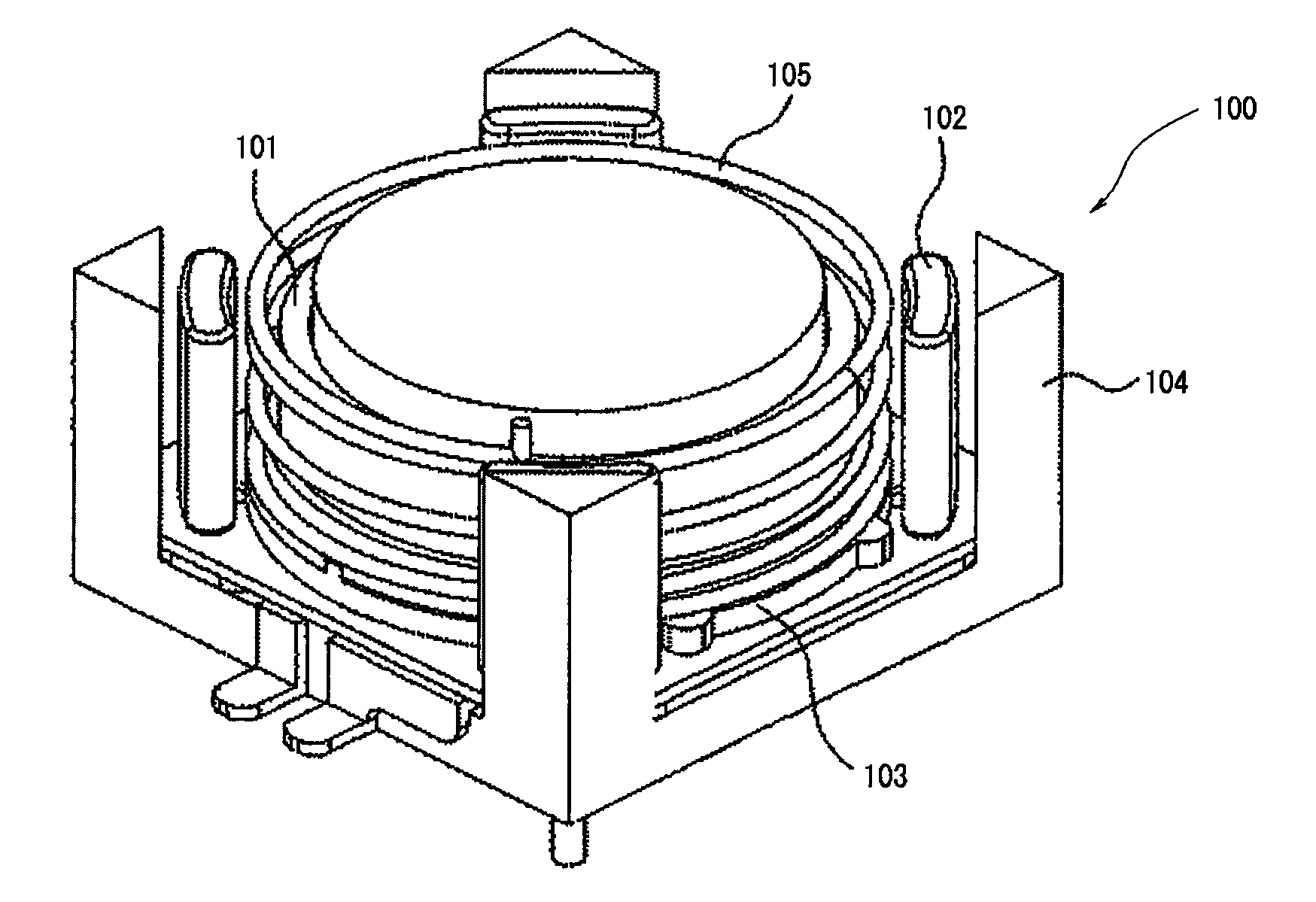
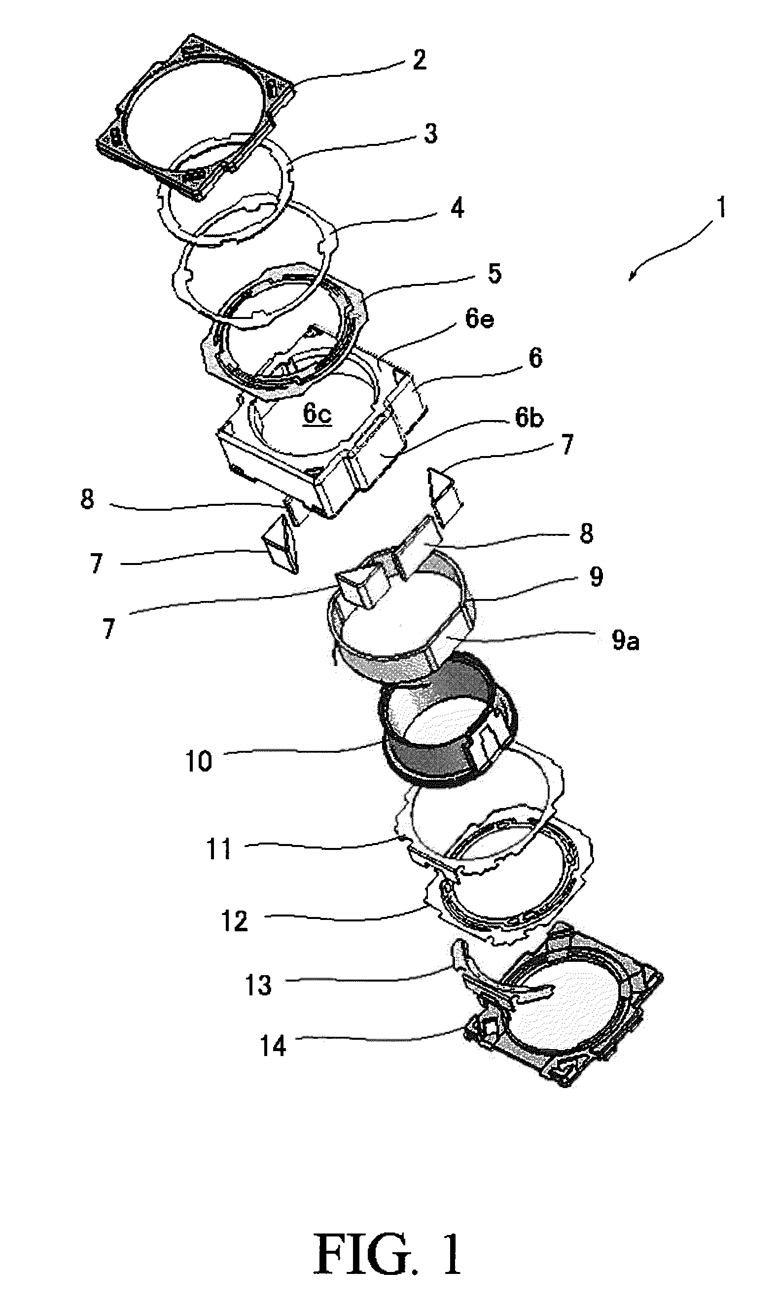
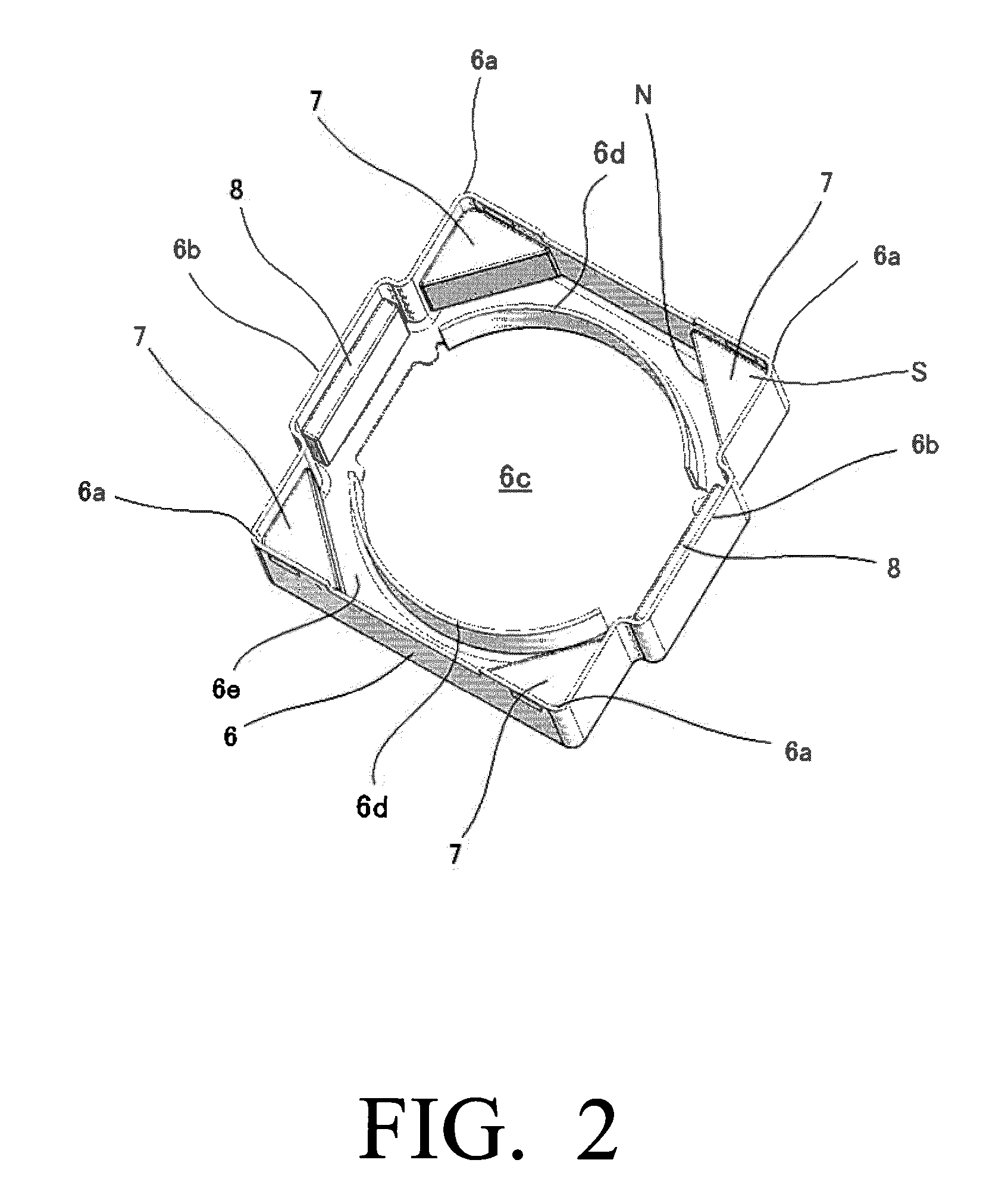
[0032]An actuator assembly 1 of a camera module according to the embodiment includes: a lens unit which constitutes an optical system of the camera module (not shown in the drawings); a holder 10 which houses the lens unit therein and is displaceable along the optical axis direction of the camera module, the holder 10 having a roughly cylindrical shape having upper and lower cylindrical end portions; a coil 9 provided on the holder 10; and a yoke 6, four main magnets 7 and two flat plate-shaped auxiliary magnets 8 which provide a magnetic field to the coil 9. The yoke 6 has a roughly rectangular and relatively thin box shape of which bottom side is opened so that the yoke 6 is defined by four side wall portions 6b and a top plate portion 6e, and the yoke 6 also has an opening 6c formed in the top plate portion 6e for receiving the holder 10 an...


PUM


Abstract

A camera module includes a lens unit; a holder which houses the lens unit therein and is displaceable along an optical axis direction of the lens unit; a coil provided on the holder; a yoke, four main magnets and two flat plate-shaped auxiliary magnets which provide a magnetic field to the coil, in which the yoke has a roughly rectangular and relatively thin box shape of which bottom side is opened so that the yoke is defined by four side wall portions and a top plate portion, and the yoke also has an opening formed in the top plate portion for receiving the holder; upper and lower leaf springs respectively attached to the upper and lower cylindrical end portions of the holder for supporting the holder so as to be displaceable along the optical axis direction; and a base which supports the yoke and the lower leaf spring. In the camera module, the coil is formed into a roughly cylindrical shape having two opposite outer circumferential flat surfaces, each of the four main magnets has a triangle block shape and they are respectively arranged at the four corner portions inside the yoke, and the two auxiliary magnets are respectively arranged on a pair of the opposite side wall portions of the yoke so as to face the corresponding outer circumferential flat surfaces of the coil, respectively.

Description

BACKGROUND OF THE INVENTION[0001]1. Field of the Invention[0002]This invention relates to a camera module, and more specifically to a camera module that can be used in small-sized electronic apparatuses such as digital cameras, camera-equipped cellular phones and the like.[0003]2. Description of the Prior Art[0004]A camera module having a function of displacing a lens unit in a direction of an optical axis of the lens unit is used in relatively small-sized digital cameras, camera-equipped cellular phones and the like. This function is used for providing an autofocus function and / or zoom function, and is achieved by an interaction between a magnetic field generated by an electrical current flowing in a coil and a magnetic field generated by a yoke and magnets provided on the yoke. Recently, camera modules to be mounted in camera-equipped cellular phones are required to further reduce size and shape thereof.[0005]FIG. 4 shows an actuator assembly for providing an autofocus function us...

Claims


Application Information

Patent Timeline
IPC IPC(8): H04N5/225
CPCH04N5/2254H04N5/2257H04N23/57H04N23/55G03B5/00G03B7/04G03B30/00G03B2205/0069
Inventor OSAKA, TOMOHIKO
Owner MITSUMI ELECTRIC CO LTD
Why Eureka
Try Eureka